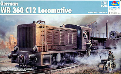
| Trumpeter WR-360 C-12 Locomotive in 1/35 |
|
Started: March / 2012 Finished: November / 2014 |
This
is one of those modeling projects that you start during a furious
drive, but have no guarantee that will hit the end... The idea
appeared after finding several interesting photos of the WR360
locomotive, like this one:
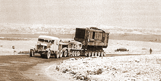
Beautiful, eh? But I'd need the Pioneer and the Famo, not to mention the dolly. And besides, that's not exactly the proper place for a manouver locomotive. Yep, the WR360 was a diesel-electric locomotive, meaning that it didn't have traction enough to pull large compositions. It was used as a tractor unit for railroad guns, but its main use was in managing and organizing compositions in large railway terminals. Anyway, a visit to Austria called my attention to Lake Grotto, a major gypsum mine confiscated by the Germans during WWII to house the production of the Heinkel He-162 in the safety of underground tunnels. At this point I started to think in a WR360 pulling a flatbed wagon out of such a tunnel with a partially assembled He-162 on top of it... Besides the 1/35 scale Trumpeter WR360 offering, I also had Trumpeter's railway gondola in 1/35 and a Revell He-162 in 1/32 in my stash. My promise to finish as many halted projects as possible would have to wait.
1/35 scale trains are pretty much like AFVs, except that thei are bigger, and heavier. Or so I thought. Before starting to remove parts from the sprues, I gathered as many references as possible, and they are not many. Internet was a big help here, because altough both kits (the WR360 and the wagon) were well molded, I was able to find many faults in the WR 360. Wagons are commonly modified in the field, but not locomotives. The WR 360 was produced in a number of versions, and I stuck to the box version (C12) in order to minimize the necessary additions.
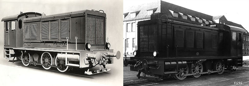
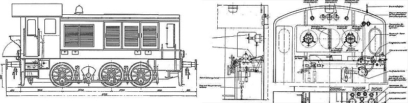
My initial research revealed that it was almost impossible to find two post-war photos of WR 360s with similar cabins. making even more difficult to find reliable photos of them during the war. I then elected to adopt a mixed approach, including details which would make sense in a diesel-electric locomotive, without changing the basic cabin layout since it seemed basically correct. Other sources of variations are the wheels, brakes and all those pressure reservoirs and piping under the engine. I decided to start with the latter.
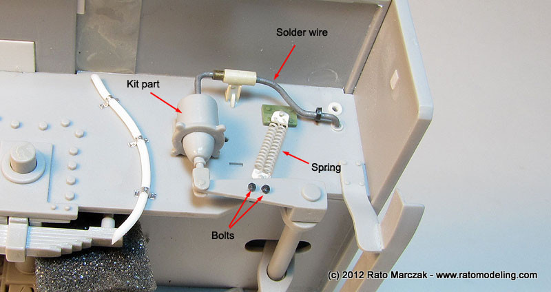
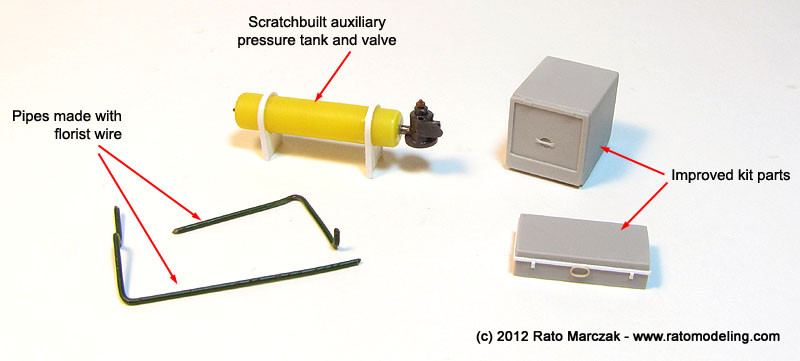
Comparison of the kit parts with photos of the real thing showed that Trumpeter simplified several details on the underside of the chassi, and not all of them are invisible. The master brake system was the part to recieve improvements. The brake cylinder is provided in the kit, but no piping, neither the pull-back springs so visible in the photos. I added the missing details, and scratchbuilt the brake auxiliary pressure tank, valves and the associated piping.
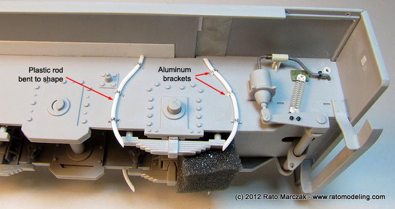
Next, I added the sand dispenser hoses installed on both sides of the rearmost wheel. They were made with plastic rod bend to shape and fixed in place with Aluminum clamps:
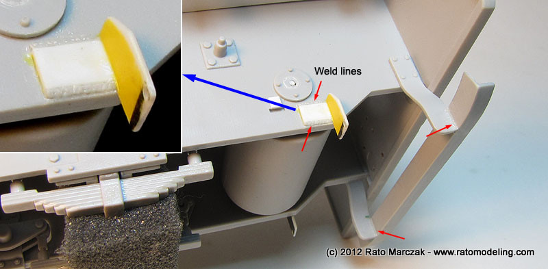
Althoug not removed from the sprues at this point, the brake shoes also had pull-back springs. Apparently this was a field addition since the type of installation varies a lot from a photo to other. I added the spring support for the shoes and took care to represent the weld lines wherever it was visible. This was done by gluing pieces of stretched sprue and soaking the area with liquid cement. Once the stretched sprue was soft, an old, dull X-acto knife was used to produce the textures:
Moving to the upper front side of the chassis, I detailed the handrail supports with plastic card and bolts to simulate the steel plates used on the real thing. I also added a few weld lines here and there:
On the rear area, I changed the conductor's seat support (more on that later) and added a plate to hold what I understand is the handbrake lever.
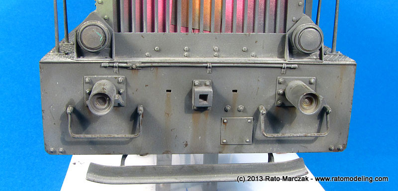
The front and rear plate of the chassis recieved several improvements, like electrical hoses for the lights, access plates and bolts. It is important to mention that I didn't like the way Trumpeter has molded the bumpers, so I decided to leave them out until I come up with something better.
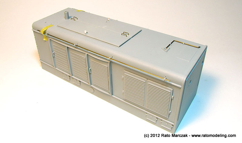
Up to that point, the fit of all parts was very good. The only really annoying thing was the number of ejection pin marks. Eliminating them (at least where they would be visible) slowed down the parts preparation significantly. On the other hand, Trumpeter made good use of slide molding to produce an amazing one-part engine cover. Mine came warped, but once you install the access hatches and drop it on the lower chassis everything aligns well. Added details here included the compressed air line to the whistle and the plastic side guards replaced by metal rods:
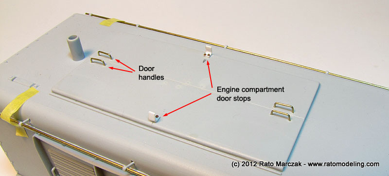
The main engine doors had missing details as well. I added new handles made from brass rod and the characteristic stops which prevent the doors from flipping over the sides. Still missing are six hooks (three per side) used to raise the locomotive. I've seen some fellow modelers adding strap hinges to the doors, but to the best of my knowledge, all a C12 had there was piano hinges.
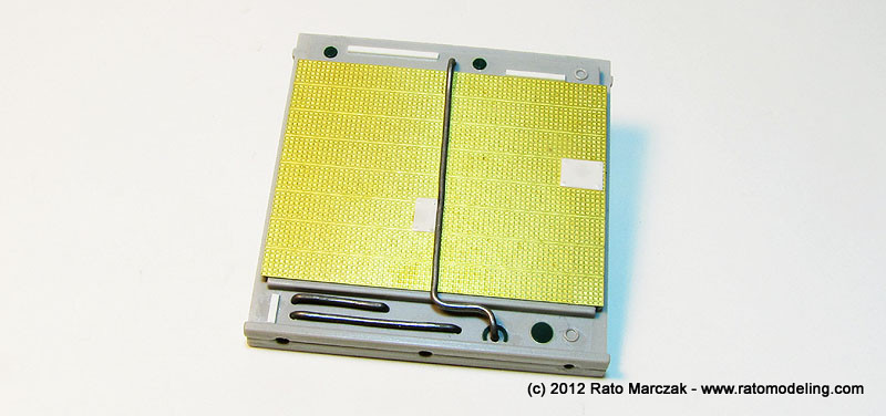
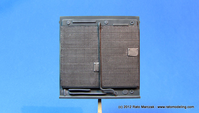
The radiator of the diesel engine must be painted and finished before the cover is glued to the bed. I used stock parts, which include a nice PE grille, but also added some gizmology that a repaired unit should show... artistic licence:
Except for the aforementioned hooks, the engine cover was done:
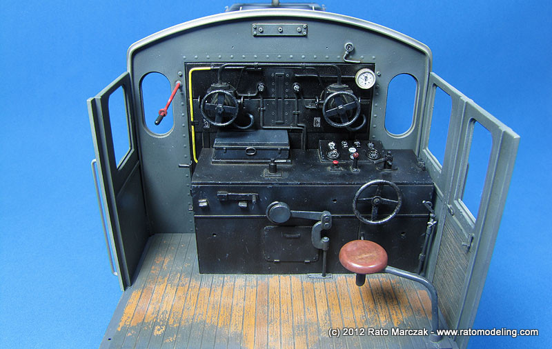
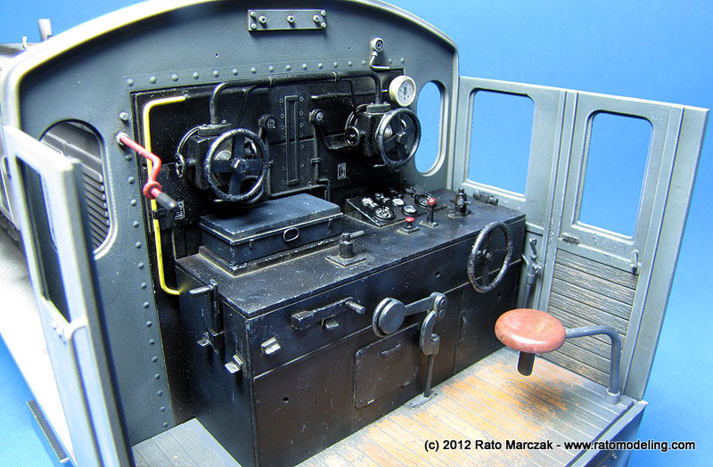
The next area to be tackled was the conductor's cabin. Finding documentation for its interior was a tough task. In the end, I decided not to depict all the instruments, levers and handles neatly arranged like if the locomotive had just left the factory. I wanted a war weary machine, and therefore field modifications, additions and deletions were common in an area so crammed with mechanical stuff. Therefore, some manometers and plumbing are adapted... I reasoned that this would be much more interesting environment to a heavy weathering treatment later. Here is the result by then:
I used different materials, from plastic, brass, Aluminum in wire and tubing form. I developed an easier way to manufacture Aluminum brackets from soda can strips, and I used them almost everywhere in this project. The manometers are pieces of tubing and disks glued together. I also embossed countersunk rivets using a beading tool, while the lines of round head rivets where produced using 3D decals from MicroMark.
Still in the cabin, the conductor's bench also recieved a number of improvements:
I also added a few other details not shown in the photos, but at this point I was convinced that a careful painting would bring the office to life:
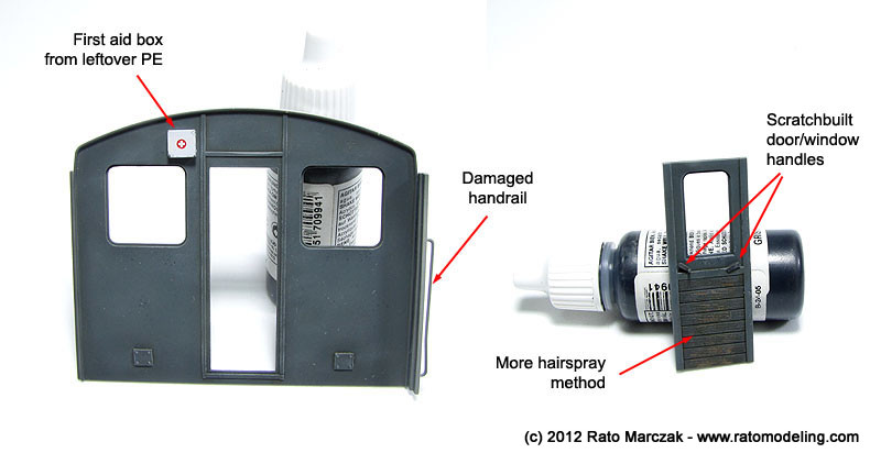
Before gluing the cabin walls, I had to take care of three things. First, smaller details had to be prepared. I added a small first aid box to be installed on one of the walls. I also had to scratchbuilt a master handle completely overlooked by Trumpeter and a crank used for who knows what:
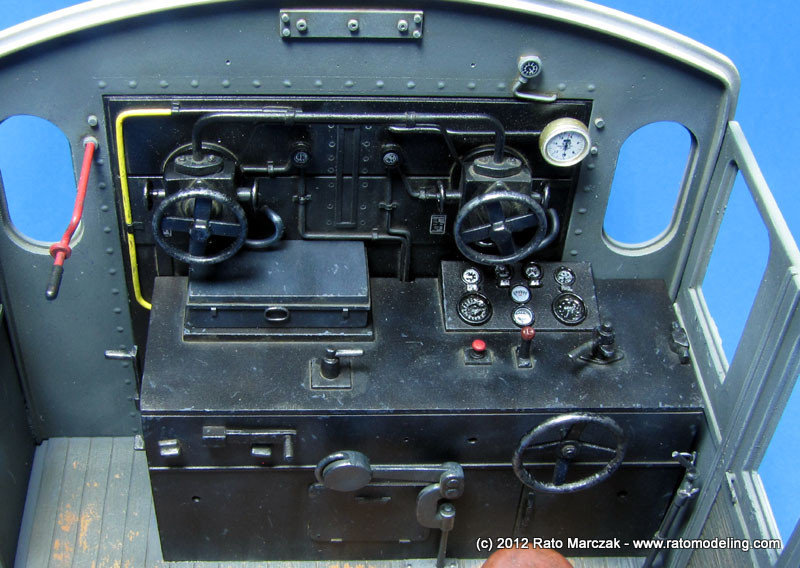
I was particularly satisfied with the way my hand wheels ended up. Trumpeter provides them as photoetched items, but I wanted to impart a more three-dimensional look to them. In order to solve that, I punched the spokes off using a punch & die tool. The spokes were lightly bent to a conical shape by pressing an embossing tool over them resting on a rubber pad. I then made rings using 0.5 mm solder wire and glued the spokes centered over them, resulting in very convincing - and truly 3D - wheels:
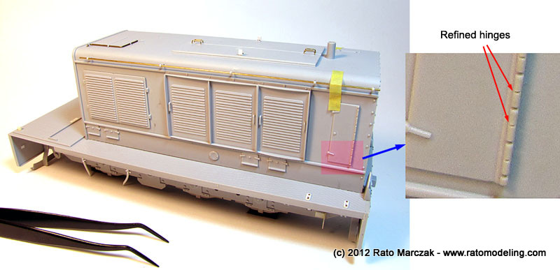
The second major work on the cabin was to improve the lateral doors. I added handles on the outer side, and a window crank on the inner sides. The port door was removed to be assembled open. In the process, I had to replace both vertical door frames (removed from the original parts) with plastic strips. Fortunately, I had a close match in my plastic bin, and didn't even had to true them:
Trumpeter provided nice PE anti-slip metal sheets to be bent and used in all the stairs and steps of the model. Their use is straighforward, and they add a lot to the plastic parts:

The exception for which Trumpeter has not provided any PE detail is the hinged platform behind the cabin's rear door. I upgraded it with left-over PE parts simulating anti-slip sheet glued atop the kit part:
To finish off the control cabin, I added a gutter to the cabin's roof. It was just a matter of gluing plastic strips along the sides of the curved roof and sanding the edges to simulate a curved sheet:
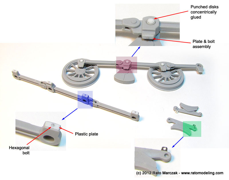
The wheels were assembled as per kit instructions, except that I decided not to glue them to the axles to make painting easier. However, most moving parts lack important details, in particular safety devices and lubricating accessories. Most of the movable parts have some kind of cap or plate to keep the lubricant from spilling out, and these are fixed in place by bolts. Since I don't know the exact terminology for these thing, the figure below shows some of these items common to old locomotives:
I took a shortcut and stashed circular disks to the shafts, maybe I'll add an hexagonal bolt later. The lubricant tub covers were made by rectangular plastic strips, with a small bolt glued atop of it:
After a halt of several weeks, I resumed work on the project. To keep some interest on it, I had to paint something, so I started with an easy thing: the radiator of the diesel engine. Nothing fancy. Some black, dark gray and steel paint, black washes and lots of drybrushing:
Contrary to my initial thought, much of the radiator could be seen through the front grille. I cemented the radiator in place, protected it with pieces of post-it notes and glued the engine cover in place. The post-it notes will protect the radiator during the whole assembly, and eventually removed throughout the grille openings. If you are assembling this model, don't forget to paint the interior of the engine cover with a dark color, because you can see a lot through the grille.
Looking around to see what I was missing to finish off the locomotive, it became clear that there wasn't much left in the sprues, and so I decided it was time to paint and assemble the conductor's cabin. I started by the floor, but soon I realized that there was a small color puzzle to solve first: which ones should be the colors of the cabin's interior? With my limited info on the subject, I reasoned that most things should be painted with the same color of the exterior camouflage, i.e. panzer gray, but it also seemed correct to leave the control bench painted in black like most engines during their civil life prior the war.
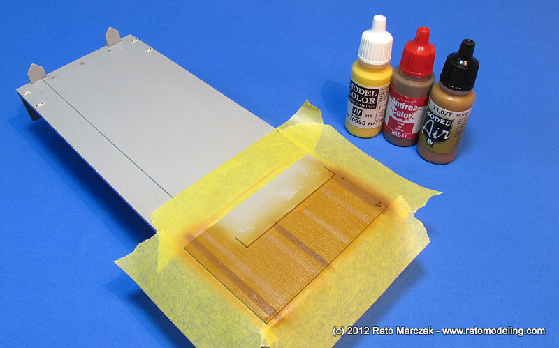
Back to the floor, the real thing was wood planked, and it would be a nice chance to use the now popular hairspray technique to simulate chipped paint. I started painting the planking with two or three shades of wood, then shot a protective layer of automotive clear gloss lacquer, and finally coated everything with a good layer of the cheapest hairspray I found in the mall:
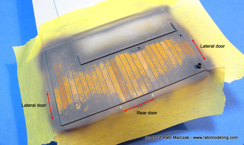
After waiting the hairspray to dry, I shot a coat of Tamiya German Gray XF-63 acrylics and dried it right after using a hair dryer. And then the fun started: I soaked the whole area with tap water and started to scrub the acrylics with a short flat brush. The wetted hairspray layer will make the paint above it to peel off easily (I'm currently writing an article explaining the method - stay tuned). I reasoned the German Gray color would flake off from the planking more heavily along trails connecting the doors. That's why I removed almost all paint from these areas:
I liked the effect, with some paint remaining along the deeper wood grain marks and into the crevices between each plank. I sealed everything with another coat of gloss varninsh and applied a Burnt Sienna oil wash to simulate grime and stains. A final coat of flat varnish sealed the wash and after that I drybrushed a light cream yellow oil to highlight the wood grain and reduce the contrast between wood colors:
The next obvious painting section was the conductor's bench and its 'control panel'. I was willing to paint those parts, but I had to hold any multi-color thoughts after checking many photos I took while visiting the Railroad Museum of Pennsylvania, because these spaces were not full of color. Instead, most of the times they are just plain black, except for a few important devices like emergency brakes, master pressure valves and the like. I airbrushed a solid layer of semi-gloss black automotive lacquer over the parts and, while the paint was still in the aibrush cup, added a few drops of white and went back to the parts to simulate fake shadows, lights and a few grimy spots.
The most fun part was to bring manometers, gauges, valves and all those typical gadgets to life. I used cockpit placards and instrument decals from various manufacturers and left over sheets to decorate them. Whenever I had a punch matching well the gauges' diameters, I'd cover the instrument with a thin clear disk to simulate the glass. Otherwise, I'd just apply a droplet of clear nail varnish. Both worked well, but nothing matchs the realism of a clear disk simulating gauges' glasses.
The same approach was used for the instruments on the conductor's bench. I think Trumpeter should have provided decals for them... To weather the area, dark gray paint was applied with a sponge along edges and corners, while Prismacolor gray pencils simulated scratches and small paint chipping. Graphite was used to bring some shine to recent scratches. Pin washes reproduced dust and dirt accumulated along edges. The final weathering step was to make a liberal use of Humbrol's Polished Steel (#27003) from their Metalcote line with both a pointed brush and sponges. I love this stuff, as they can be polished when dry, rendering the perfect 'exposed metal' look to the part.
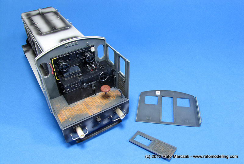
Here is a look of both assemblies together:
I deviated from the instructions at this point of the assembly. Since I had opened one of the cabin's door, it would be impossible to assemble the four cabin walls. Instead, I assembled the front and side walls using alignment tools to make the corners perfectly square. I would let this dry completely before attaching the back wall.
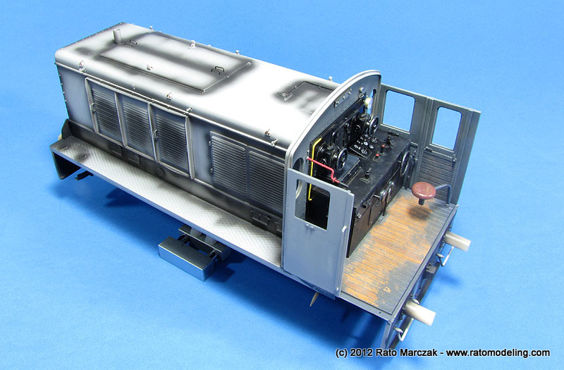
The cabin's roof are formed by two parts to be installed on the top of the cabin. It would be made removable to see the cabin's interior afterwards. And by the way, in the photos below the cabin still have a few details to be installed, besides the windows, of course:
This is how the WR-360 stood a this point. Note the pre-shading already applied along the main body:
The back wall was simply painted dark gray and weathered with scratches here and there. To add interest, I glued a first aid box from a leftover PE set, right behind the conductor's seat. The reworked door was also painted using the hairspray method. Each door recieved a couple of handles, an opening handle and a window lowering handle:
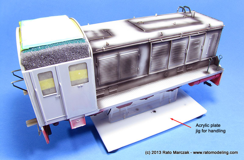
A couple of extra details were added (a few wires) before the back wall was glued in place. Careful alignment was important, as I wanted to make the cabin's roof removable to show the interior. Handling the model started to become an issue, since there were several details to be assembled on the underside (not the mention the whole brake system and wheels), and holding the model by the engine cowling was not an option because of the fragile details cemented in place (see text below).
I ended up making a jig using bolted acrylic plates. The jig securely hold the model by two axles and, although not perfect, worked well:
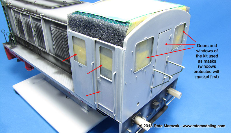
With the application of the main camouflage color approaching, I temporarily assembled the doors and windows in place to serve as masks. The trick is to apply a good coat of Maskol (or similar) to the windows and fix them in place with tape on the inner side of the cabin. Once the external paint is finished, I would just pop the windows and doors out, remove the Maskol and glue them definitely in place. I blocked the cabin's ceiling with pieces of sponge and tape.
Other details added to the hull at that point were the engine panel lockers, which were scratchbuilt from plastic bits, and the characteristic hooks on top of the engine, used to lift the cowling. Trumpeter missed both, and the latter had a master scratchbuilt and copied six times in resin. Once glued in place, the hooks were decorated with Tichy Train bolts:
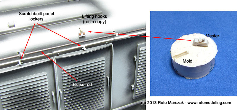
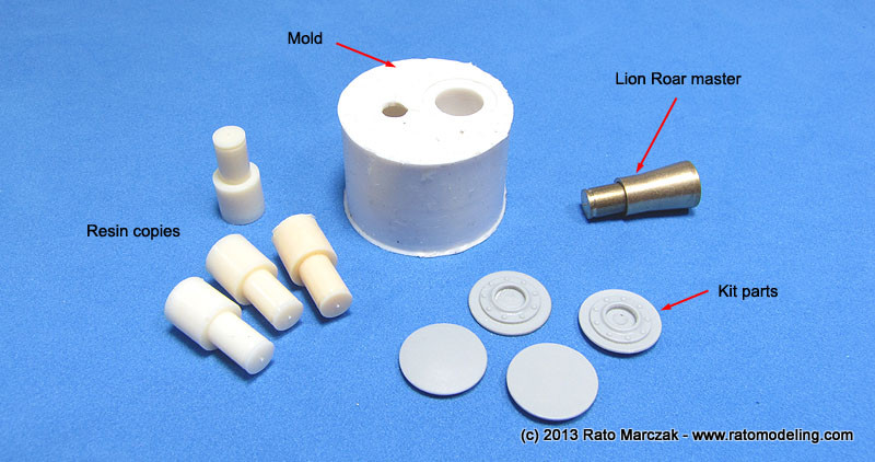
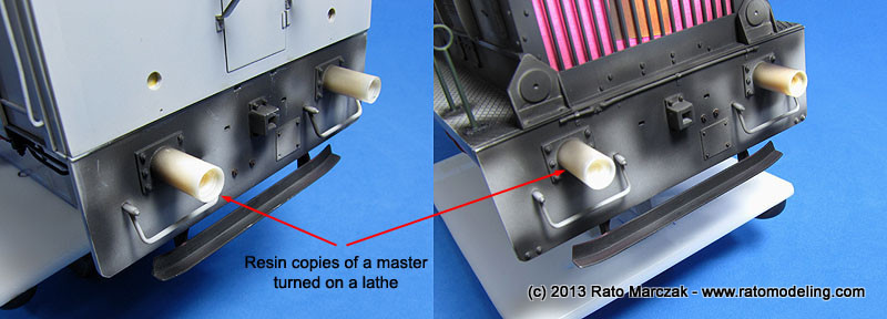
Another item which I really disliked in this kit are the side buffers of the engine. In my sample they had a visible mold shift, and these are the kind of part which never looks good without being perfectly cylindrical. Since it would be impossible to make them acceptable without reducing significantly their diameter, I opter for copying a brass item from Lion Roar (railroad flat buffer) in resin. They are workable, but all I wanted was the internal cylinder, which will later accept the buffers from the kit. The external cylinder was turned in my lathe, copied in resin, and glued to the front and rear plates in lieu of the kit parts. Once the main camouflage is finished, I would go back and install the movable parts of the buffers inside them:
Before loading my airbrush to apply the main camouflage color, I had to dig some further info about the WR-360, in particular the C-12 model. I found out that most of them (maybe all C-12s) were manufactured before the war, and only a dozen or so of them were actually produced before switching to the C-14 model, which was manufactured in much larger numbers. Supposedly, the C-12 never saw action outside the German borders, but I don't care that much (more on that later).
My point here is that before the war these engines had a less military aspect. I'm guessing that most of the WR-360 had their running area painted red like other locomotives usually are (and can be testified by color photos of the model C-14). When pressed into war service, a suitable camouflage would be in order, and I doubt the crews would disassemble such equipment just to apply a coat of Panzer Gray. Therefore, it seems reasonable that some of the red color on the underside of the engine could be seen through the panzer gray camouflage. That was the plan.
And so I started applying a solid layer of ATSF Red from Floquil railroad range - nothing could be more suitable, eh? I used the ATSF Red on the tanks and accessories too before gluing them in place. The scratchbuilt brake parts were painted red and black and cemented in place as well. These subassemblies were all painted separately and then installed because when the panzer gray color would be airbrushed, I didn't want it reaching the hidden areas of the lower engine, leaving a hint of the original red color there - just like what should happen with a crew man using a paint gun to camouflage the sides.
Once everything was dry (Floquil are enamels, taker more time than I'm used to), I painted the whole engine with Panzer Gray. While the paint was still in the airbrush cup, I added white and thinned the mix even more, and went back and applied highlights and fading here and there, particularly on the horizontal panels which should be more exposed to the sunlight and accumulated more dirt.
Then I started to apply the other camouflage colors. I used a mix of Tamiya's Dark Yellow and Deck Tan to make the tan color, while the Olivegrün (RAL 6003) is a mixture of Field Green and RLM 82 from automotive lacquers. I airbrushed both colors freehand using a Grex Genesis.XN airbrush. It was not a neat job, but I reasoned this was field applied cammo, in a rush, and using whatever paint was available (what good excuse, eh?). Of course I went back with a lighter version of the green and the tan and faded both to age them a bit as well...
Here is how it was by then:
I failed to find any documentation about specs to camouflage these things, and understandably probably never will. So the colors and pattern where an educated guess, but I had some hints from a couple of railroad modelers and camouflage scheme from a Czech magazine.
Here you can see how the red color was purposedly left visible at places to simulate a paint job made in a hurry:
And that's how it was:
After a long time working on other projects, I resumed the work on this model. Meanwhile, a great deal of time was spent reading about weathering techniques. Fortunately, we had endless resources and media on the subject, but still, it is a long learning curve on pigments, filters, washes, chipping and all that stuff that didn't exist last time when I finished a 1/35 model. I'm an old school modeler, and wanted to try some ready made products like washes and special effects.
I confess I was a bit afraid of ruining the model trying something new (to me), but I prefer to approach this phase being afraid of overdoing something than ending with those models which look like they remained 70 years under the mud... Fortunately, I made no serious mistakes, but during the process I had to constantly remind myself the goal of mildly weathering the WR-360, as an operational equipment which hasn't been submitted to much beating.
The basic steps I followed were as follows (I had to go back to some of them occasionally):
And the products primarily used for each step were:
Step 7 was applied more heavily on the front and rear of the engine. They will be further enhanced later on, as I still have to install all the coupling devices:

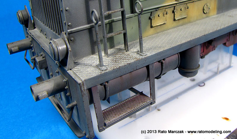
Rain/light rust streaks were also applied under the windows, handles and panel joints. Step 6 was used on horizontal surfaces, particularly the catwalk on both sides of the engine compartment. At that point, all I did was to soad the catwalk with AK Dust Effects enamel. Later on these areas will receive chipping, scratching and oil marks:
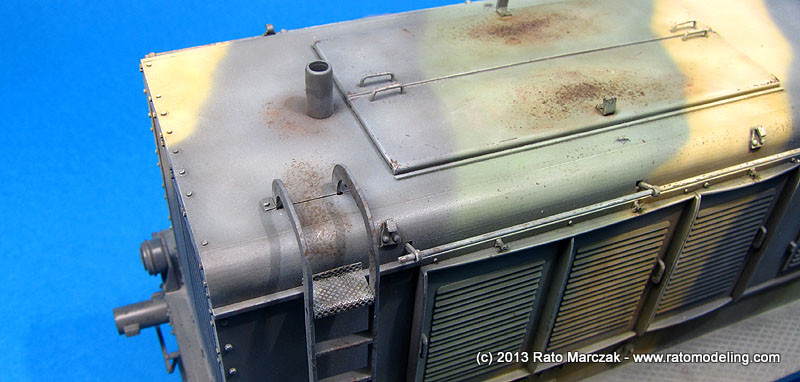
Step 8. On the top of the WR-360, I wanted to simulate a heavier rust effect, typical of areas where the metal panel presents a depression or sag, making the rain water accumulate and trigger the rusting process. I used the sponge method and acrylic paint to produce a gradation from light to dark rust colors. Pigments soaked in turpentine helped to blend everything.
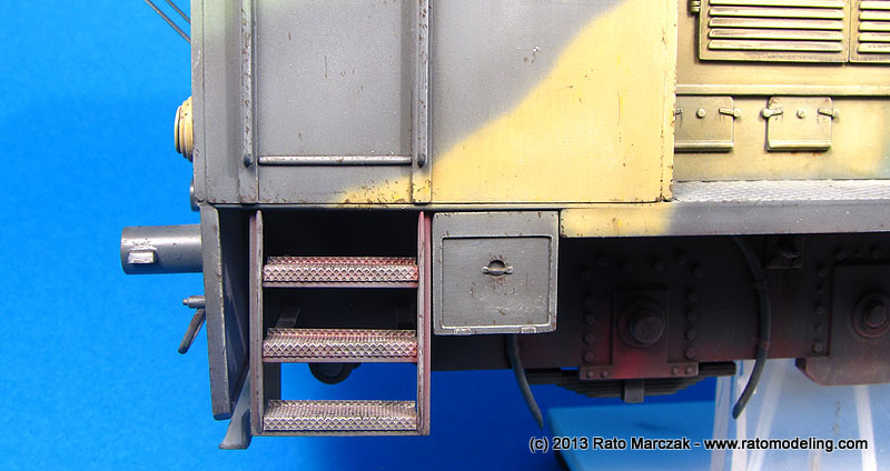
I also used the sponge method to chip the paint in the ladder entries and around the chimney:

Step 9 is something that you have to do on several passes. On the first one, I used a fine pointed brush and Vallejo acrylics to produce chipping around areas with heavier use/traffic. At that point, I limited chipping to handles, corners, and ladders. I also chipped the paint under the engine, pressure vessels and piping. Those will be retouched later with a red pencil to reveal the red undercoat:
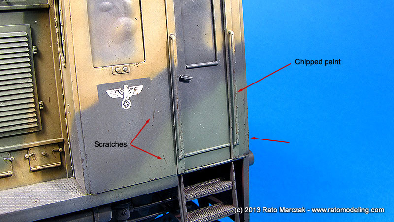
It is difficult sometimes to decide the order of the steps in order to not destroy the previous ones. It also requires good judgement to keep the balance, keeping in mind the severity of the weathering you want for the subject:
For insance, chipping on the top of the lights may sound strange at first, but it is possible that crew would step on it while servicing the engine. By alternating steps 6 and 9 you can simulate old or new chipping. Later, colored pencils will be used to enhance recent chipping with a lighter color of the camouflage:
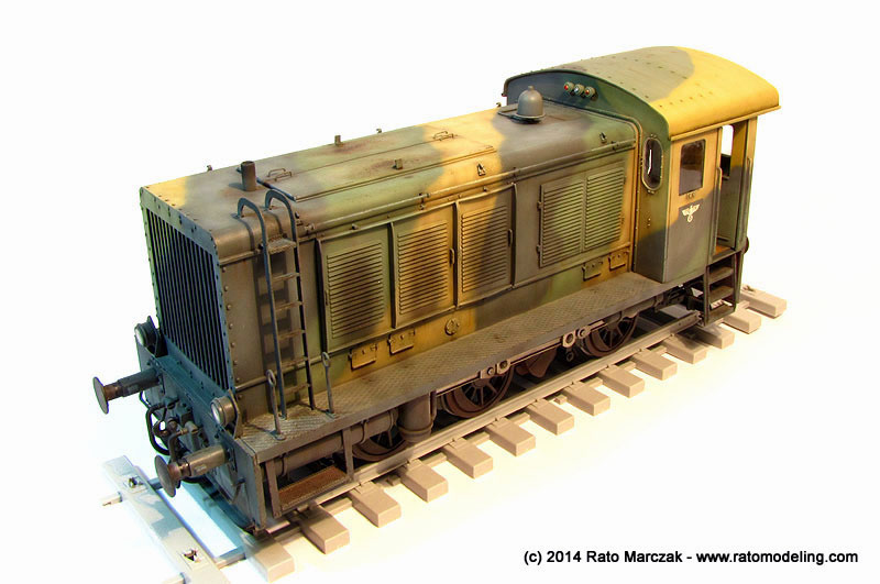
As expected, the washes, filters and effects darkened considerably the overall finish. And there will be no final flat coat on the model, which usually lighten the colors a bit (a final flat coat would weak considerably the effect produced by pigments). That's another reason why it is important to fade the camouflage colors to a good extent, even in larger scales such as 1/35:

As I said before, many of the steps may have to be reapeated as I proceed with the weathering.
While I proceeded with the weathering on the engine body, I decided to use a different method to weather the conductor's cabin roof. I simulated rusted spots using paint, pigments and white spirit as usual, but instead of using dedicated fluids to simulate the corresponding streaks, I experimented using the pigments for that. It was just a matter of depositing a small amount of rust colored pigments on the starting points and dragging it downwards using a flat brush. It worked pretty well. However, I discovered that commercial pigments like AK and MiG may not be as intense as good quality pastel chalks are. Exactly the opposite of what is advertised by modeling pigments' manufacturers. Living and learning...
And while at it, I also simulated grime accumulated along the gutters playing with artists oils and white spirit.
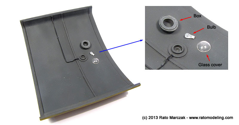
On the bottom side of the roof, a lighting system was adapted using the kit parts. I turned a bulb from a piece of clear sprue and thermoformed a glass cover using acetate. A conduit was shaped to run from the side to the luminaire, and small pieces of aluminum foil formed the clamps. Judging from photos of other engines of the time, I suspect these roofs had a bare wood finish on the internal side... well, blame Trumpeter:
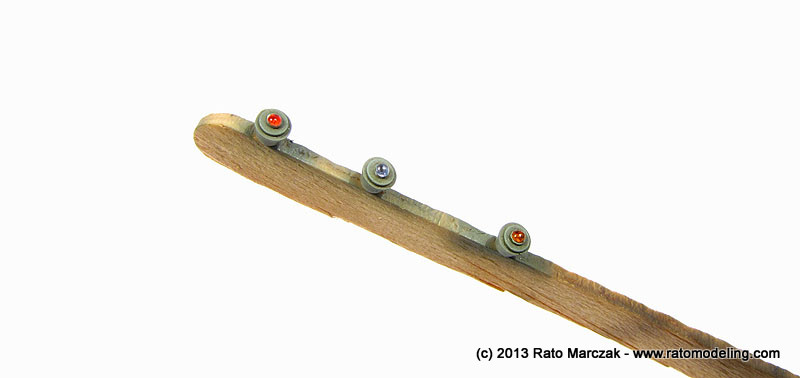
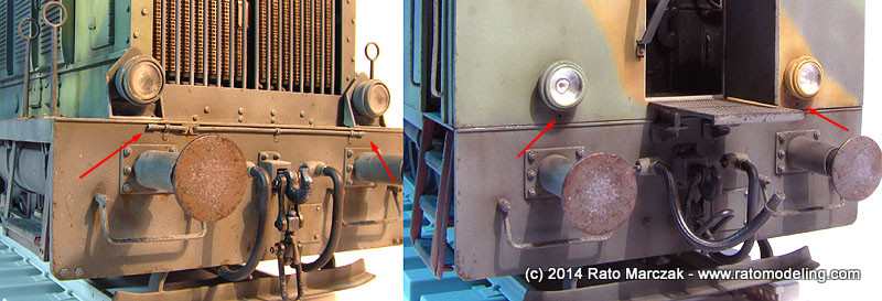
Trying to finish off the remaining details of the engine, I modified the kit lenses to accept stretched clear sprue mushroomed over a candle. They were painted with clear paints before being permanently attached to holes previously drilled. I don't have a clue whether the colors are correct or not:
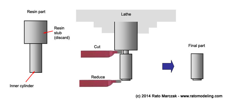
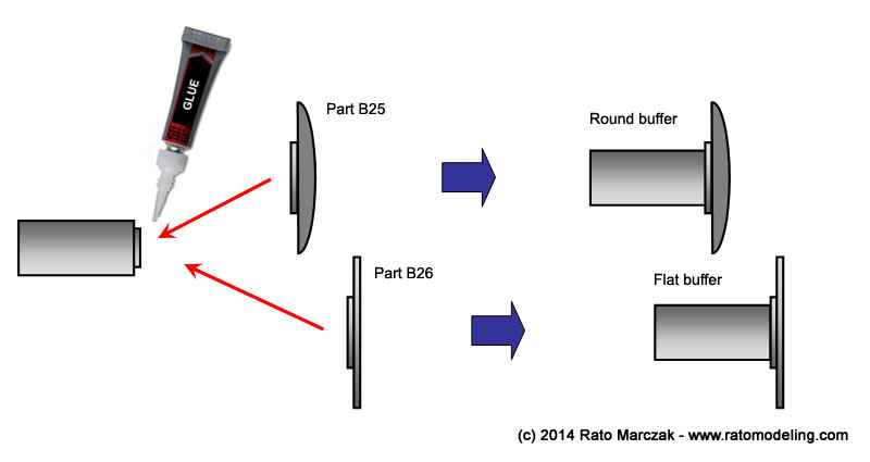
Still on the details of the engine, I had to finish the coupling system and the buffers. As mentioned above, kit parts C10 and C11 were replaced by two resin, improved ones. The outer cylinder of the buffers were glued to the front and rear plates of the chassis as you saw in the photos. The task then was to finish the movable parts of the buffers. The resin inner cylinder was cut to size and glued to the round and flat buffers (they alternate sides at the front and the rear of the engine). In order to do so, I installed the resin parts on a lathe and cut them to the correct length. I also turned a small step at the end of the cylinder to accept the kit's buffers, like in the instructions:
To weather the buffers/cylinders was a difficult task. Photos of railroad stock and engines show that if there is a part of the equipment that was not cared that much, they were the buffers - well, they are made to hit other buffers, afterall... My plan was to simulate buffers that were once overpainted with panzer grey and weathered heavily due to heavy work. So I applied factory color (black), then a light coat of panzer grey, and everything went out of control after that. Kidding aside, except for these two initial paint coats, everything was a bit of experiment to me, methods and sequence of application. The steps sequence I used were basically the following:
1. Primer
2. Semi-gloss black: this was a factory applied color. I used automotive semi-gloss paint to avoid the need of clear coats later and to resist to washes and weathering products.
3. Maskol: I used Maskol applied with a sponge over the buffers to make a heavy grey paint chipping (next step). Used on the buffers, only.
4. Panzer grey: this was the camouflage color that - I guessed - was overpainted on the engine when pressed into military service. I used a lightened version of Tamiya XF-63.
5. Paint chipping: the underneath Maskol was removed with a pencil eraser to show the black color.
6. Dry-brushing: Light grey oils were dry-brushed on steps and bolt heads, mostly on the back side of the buffers.
7. Dark rust: older rust spots were simulated using Vallejo paints and the dry-sponge method. The effect was applied on the front face of the buffers, trying to concentrate the effect on the perimeter of the disks, and also on the front part of the cylinders (Zone 2 - see text below).
8. Light rust: more recent rust spots like in step 6, except that I used a finer sponge and a more reddish color..
9. Dusting: light dust pigments thinned with Windex was generously applied over the parts. Once dry, excess was partially removed with a flat brush.
10. Exposed metal: Humbrol Polished Steel was applied with a sponge on the center areas of the buffers. This was necessary to simulate the effects of mechanical contact between buffers.
11. Metal pitting: Pitting was simulated by hitting a 6B pencil randomly over the buffers, producing tiny dark, yet metallic, spots.
At this point the buffers were virtually done. This was the result of these mere 11 steps:

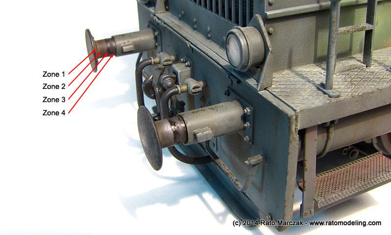
However, the cylinders still needed treatment. Since these are movable, lubricated parts, some reasoning is necessary. Under impact of another buffer, the buffer cylinder acts as a suspention, moving telescopically into the outer cylinder. Therefore, I devised four basic zones along the former:
- Zone 1 is basically the flange that connects the buffer to the cylinder. Therefore, it only collects dust and grime, and may show traces of the panzer grey.
- Zone 2 is the portion of the inner cylinder that never enters into the outer one. It may rust a bit, but may also show some remains of the polished steel due to grease stains.
- Zone 3 is the complicated one, because it marks the end of the travel length of the buffer system. Then, after some time in service, all the grease used to lubricate the cylinders end up in a messy smudge ring around zone 3, plus grime, dust, grass, deck cards, cigarette butts, engagement rings, you name it... Lost something? Try looking there!
- Zone 4 is the working length of the cylinder, which actually enters into the outer one during operation. It is common to apply grease in large quantities around this area, but most of it is pushed forth to Zone 3. The attrition between the cylinders and the lubricant make this zone mostly exposed metal.
So, how to weather these zones? This is what I did:
12. Dark dust: Further darker dusting diluted with Windex was applied on the back side of the buffers and Zone 1.
13. Exposed metal: Humbrol Polished Steel was dry-brushed circumferentially along Zone 4. This produced a faint metallic sheen randomly spread around the telescoping length of the cylinder.
Zone 2 was left as it was, but I still had to simulate the grease smudge on Zone 3.
14. Grease smudge: In order replicate this effect on Zone 3, I installed a disk on my lathe covered with a double sided adhesive tape. This allowed me to mount the almost-finished buffers without the risk of damaging the painted areas. I prepared a mix of Tamiya Smoke (X-19) and Humbrol Smoke pigment and applied it with a brush while turning the lathe at minimum speed. By zigzagging the paintbrush just a tad you avoid a perfectly circular mark. Don't simply brush the mix, try dabbing the point of the paintbrush. In addition, small blobs of the smudge sometimes left the paintbrush, simulating larger spots of grease. The pigment made most of the X-19 sheen disappear, so I had to come back and apply gummy (partially dry) X-19 randomly with a toothpic around Zone 3 and the aft end of Zone 4. This resulted in a mix of old (semi-flat) and recent (gloss) grease simulation:
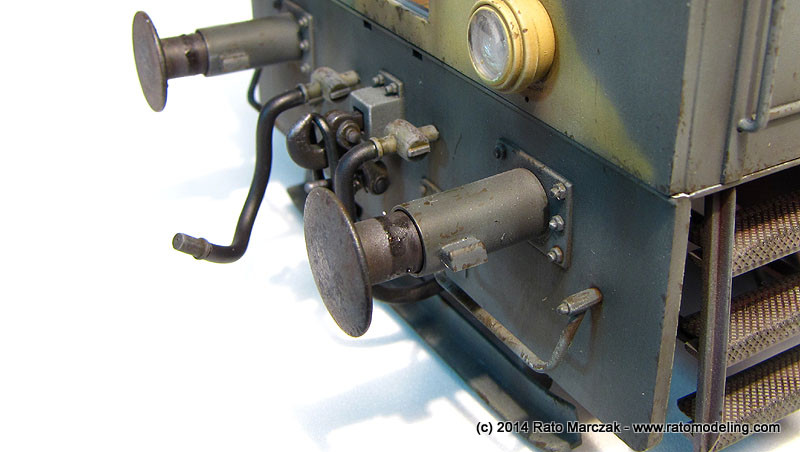
Once everything was dry, the finished buffers were glued in the outer cylinders:
And this was the result of steps 12-14:
The coupling mechanisms were next. I want them movable, at least the aft one, since it must connect the flatbed later. I used a method that master modeler Rodney Williams taught me. Basically, I drilled holes where the pins went and inserted a plastic rod which was 'mushroomed' by a lit incense (not a candle, as shown below):
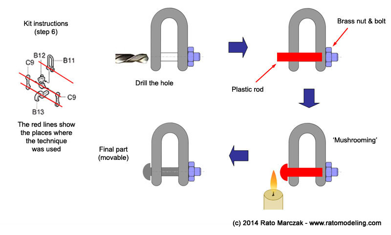
I ended up using this method for all connector pins. The bolts & studs are brass items from Precision Harware. The parts were individually painted with semi-gloss black automotive lacquer, dusted with pigments and chipped with polished steel using a sponge.
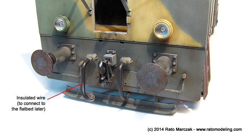
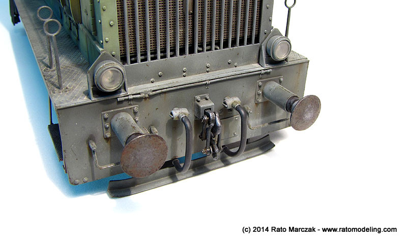
As you can see in the photos, the vacuum and steam hoses (parts C6) were painted and glued in place. An eagle eye will note that I bent the hoses slightly to make them look more natural. One of the hoses on the aft was replaced by an insulated wire of suitable diameter, so I can shape it to connect to the respective one in the flatbed later.
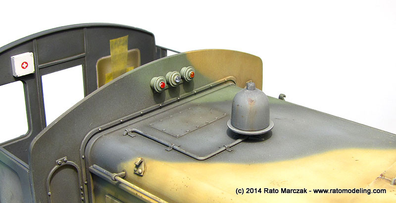
The masks of the lights were finally removed, revealing the bulbs made earlier with clear sprue. The traffic lights atop the cabin were glued in place, as well as the whistle.

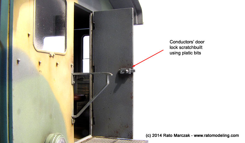
And so I was finally on the last bits. The conductor's door was cemented open, and a crude lock was made from plastic bits. The little access platform was also glued in place, and unfortunately it hides part of the coupling details under it. All the windows were installed and light earth color pigments were powdered over them, then removed with a soft make-up brush, leaving accumulated dust around their borders. The window on the driving side was cut in about half its height to look like if it was lowered. I even simulated one of the windows cracked - it is a nice effect, but difficult to capture in the photos.

The lateral door was also installed in open position, but first I had to add a metal strip running over the top of both wall sections. This was glued with epoxy glue and is a necessary measure to adde stiffness to the assembly, particularly in the case of a removable roof. The atmospheric view of the cabin pleased me, I just hoped I had taken the photos under natural light:
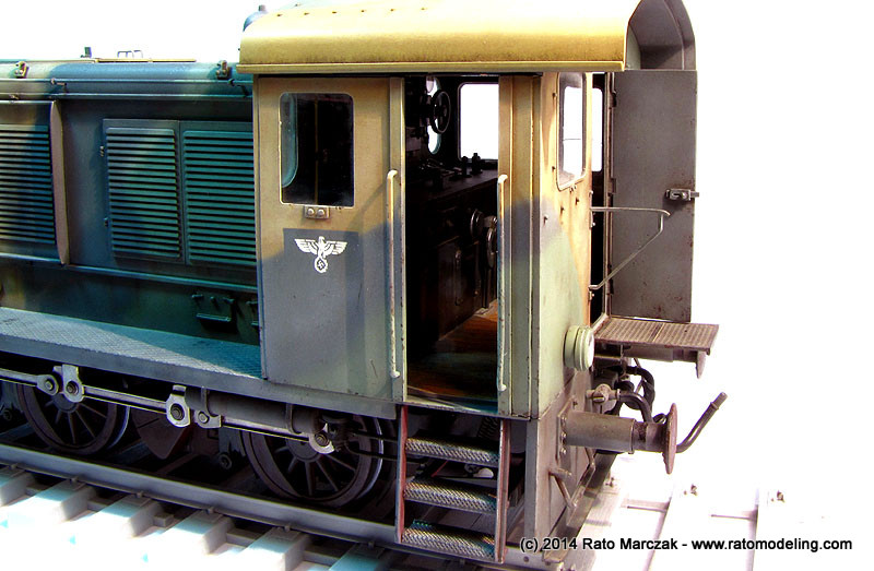
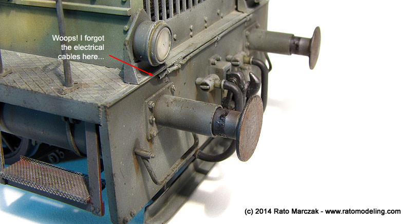
When processing these photos I noted that I forgot to install the electrical cables of all four lights. The holes and conduits are there, but the next time you will see the model will probably be during the diorama construction:
All the work on the brake system also payed off, albeit hidden under the ladder, it was a real improvement over the kit parts. The movable parts of the wheels should be a tad more greased to my taste, maybe I'll add more later:

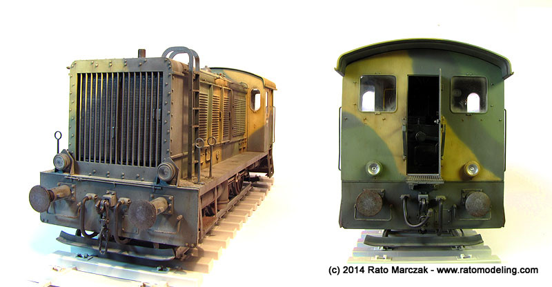
I still have to add scratchs and chipped paint revealing the red color under the camouflage. This will be done with a colored pencil later on. For now, I can call it done:
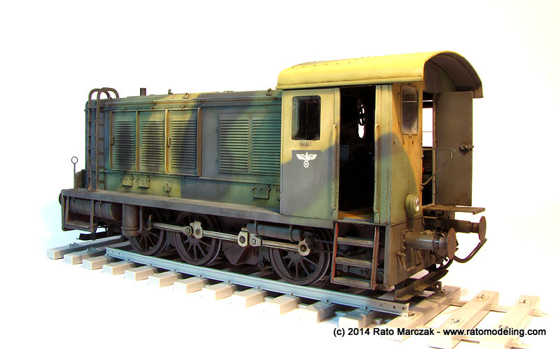
The removable roof doesn't seem a so good idea now... The fit is so tight that everytime I remove/put it back I'm afraid some paint will be damaged. So far so good. Anyway it would not make any sense in not allowing to see all the details in the cabin:
In the next installment, I'll just add a couple of shots showing the red paint scratches and the electrical connections, maybe. For now, these are the final photos of this long project:
/
Beautiful, eh? But I'd need the Pioneer and the Famo, not to mention the dolly. And besides, that's not exactly the proper place for a manouver locomotive. Yep, the WR360 was a diesel-electric locomotive, meaning that it didn't have traction enough to pull large compositions. It was used as a tractor unit for railroad guns, but its main use was in managing and organizing compositions in large railway terminals. Anyway, a visit to Austria called my attention to Lake Grotto, a major gypsum mine confiscated by the Germans during WWII to house the production of the Heinkel He-162 in the safety of underground tunnels. At this point I started to think in a WR360 pulling a flatbed wagon out of such a tunnel with a partially assembled He-162 on top of it... Besides the 1/35 scale Trumpeter WR360 offering, I also had Trumpeter's railway gondola in 1/35 and a Revell He-162 in 1/32 in my stash. My promise to finish as many halted projects as possible would have to wait.
1/35 scale trains are pretty much like AFVs, except that thei are bigger, and heavier. Or so I thought. Before starting to remove parts from the sprues, I gathered as many references as possible, and they are not many. Internet was a big help here, because altough both kits (the WR360 and the wagon) were well molded, I was able to find many faults in the WR 360. Wagons are commonly modified in the field, but not locomotives. The WR 360 was produced in a number of versions, and I stuck to the box version (C12) in order to minimize the necessary additions.
My initial research revealed that it was almost impossible to find two post-war photos of WR 360s with similar cabins. making even more difficult to find reliable photos of them during the war. I then elected to adopt a mixed approach, including details which would make sense in a diesel-electric locomotive, without changing the basic cabin layout since it seemed basically correct. Other sources of variations are the wheels, brakes and all those pressure reservoirs and piping under the engine. I decided to start with the latter.
Comparison of the kit parts with photos of the real thing showed that Trumpeter simplified several details on the underside of the chassi, and not all of them are invisible. The master brake system was the part to recieve improvements. The brake cylinder is provided in the kit, but no piping, neither the pull-back springs so visible in the photos. I added the missing details, and scratchbuilt the brake auxiliary pressure tank, valves and the associated piping.
Next, I added the sand dispenser hoses installed on both sides of the rearmost wheel. They were made with plastic rod bend to shape and fixed in place with Aluminum clamps:
Althoug not removed from the sprues at this point, the brake shoes also had pull-back springs. Apparently this was a field addition since the type of installation varies a lot from a photo to other. I added the spring support for the shoes and took care to represent the weld lines wherever it was visible. This was done by gluing pieces of stretched sprue and soaking the area with liquid cement. Once the stretched sprue was soft, an old, dull X-acto knife was used to produce the textures:
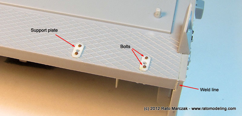
Moving to the upper front side of the chassis, I detailed the handrail supports with plastic card and bolts to simulate the steel plates used on the real thing. I also added a few weld lines here and there:
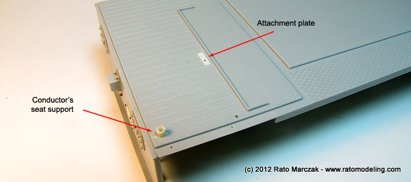
On the rear area, I changed the conductor's seat support (more on that later) and added a plate to hold what I understand is the handbrake lever.
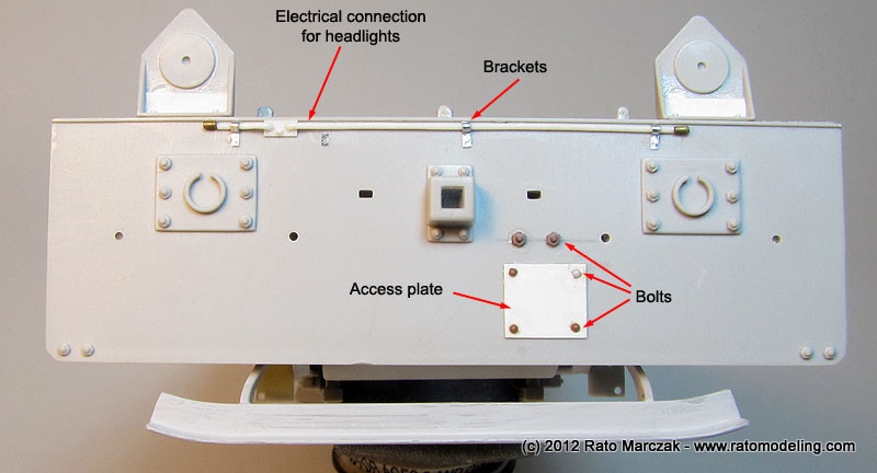
The front and rear plate of the chassis recieved several improvements, like electrical hoses for the lights, access plates and bolts. It is important to mention that I didn't like the way Trumpeter has molded the bumpers, so I decided to leave them out until I come up with something better.
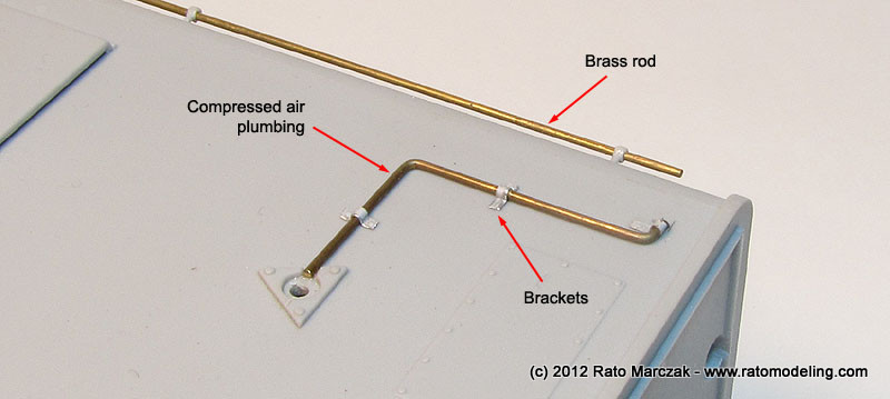
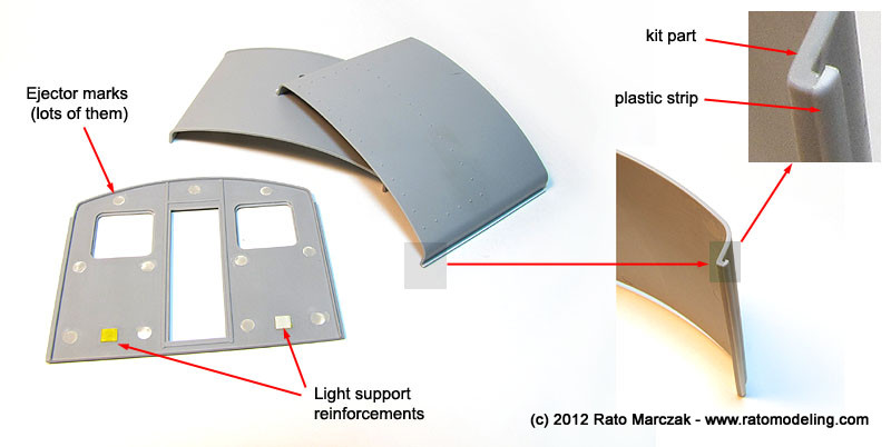
Up to that point, the fit of all parts was very good. The only really annoying thing was the number of ejection pin marks. Eliminating them (at least where they would be visible) slowed down the parts preparation significantly. On the other hand, Trumpeter made good use of slide molding to produce an amazing one-part engine cover. Mine came warped, but once you install the access hatches and drop it on the lower chassis everything aligns well. Added details here included the compressed air line to the whistle and the plastic side guards replaced by metal rods:
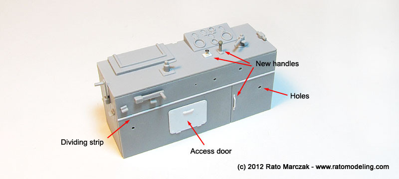
The main engine doors had missing details as well. I added new handles made from brass rod and the characteristic stops which prevent the doors from flipping over the sides. Still missing are six hooks (three per side) used to raise the locomotive. I've seen some fellow modelers adding strap hinges to the doors, but to the best of my knowledge, all a C12 had there was piano hinges.
The radiator of the diesel engine must be painted and finished before the cover is glued to the bed. I used stock parts, which include a nice PE grille, but also added some gizmology that a repaired unit should show... artistic licence:
Except for the aforementioned hooks, the engine cover was done:
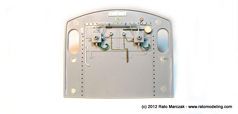
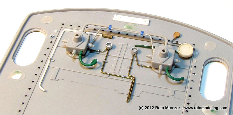
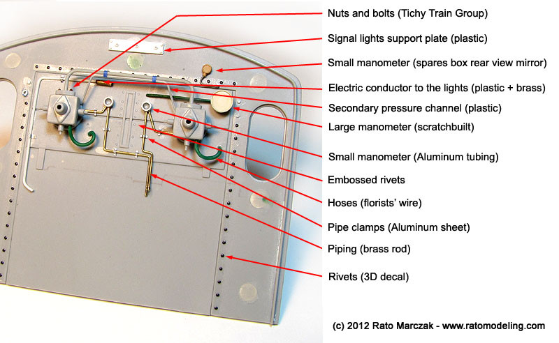
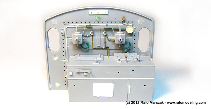
The next area to be tackled was the conductor's cabin. Finding documentation for its interior was a tough task. In the end, I decided not to depict all the instruments, levers and handles neatly arranged like if the locomotive had just left the factory. I wanted a war weary machine, and therefore field modifications, additions and deletions were common in an area so crammed with mechanical stuff. Therefore, some manometers and plumbing are adapted... I reasoned that this would be much more interesting environment to a heavy weathering treatment later. Here is the result by then:
I used different materials, from plastic, brass, Aluminum in wire and tubing form. I developed an easier way to manufacture Aluminum brackets from soda can strips, and I used them almost everywhere in this project. The manometers are pieces of tubing and disks glued together. I also embossed countersunk rivets using a beading tool, while the lines of round head rivets where produced using 3D decals from MicroMark.
Still in the cabin, the conductor's bench also recieved a number of improvements:
I also added a few other details not shown in the photos, but at this point I was convinced that a careful painting would bring the office to life:
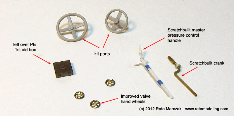
Before gluing the cabin walls, I had to take care of three things. First, smaller details had to be prepared. I added a small first aid box to be installed on one of the walls. I also had to scratchbuilt a master handle completely overlooked by Trumpeter and a crank used for who knows what:
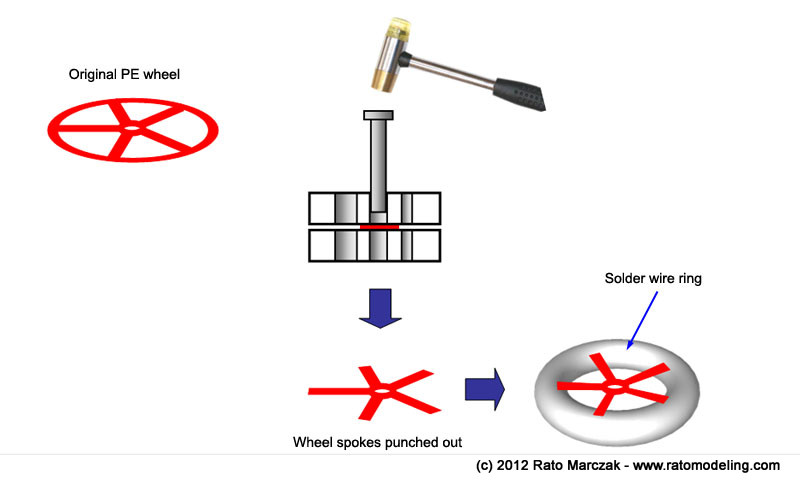
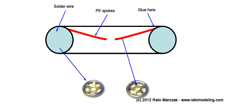
I was particularly satisfied with the way my hand wheels ended up. Trumpeter provides them as photoetched items, but I wanted to impart a more three-dimensional look to them. In order to solve that, I punched the spokes off using a punch & die tool. The spokes were lightly bent to a conical shape by pressing an embossing tool over them resting on a rubber pad. I then made rings using 0.5 mm solder wire and glued the spokes centered over them, resulting in very convincing - and truly 3D - wheels:
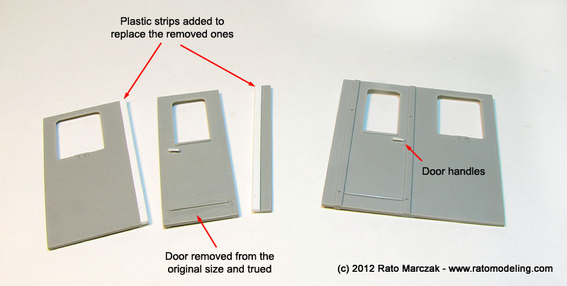
The second major work on the cabin was to improve the lateral doors. I added handles on the outer side, and a window crank on the inner sides. The port door was removed to be assembled open. In the process, I had to replace both vertical door frames (removed from the original parts) with plastic strips. Fortunately, I had a close match in my plastic bin, and didn't even had to true them:
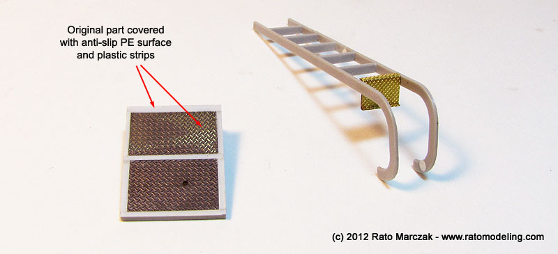
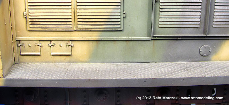
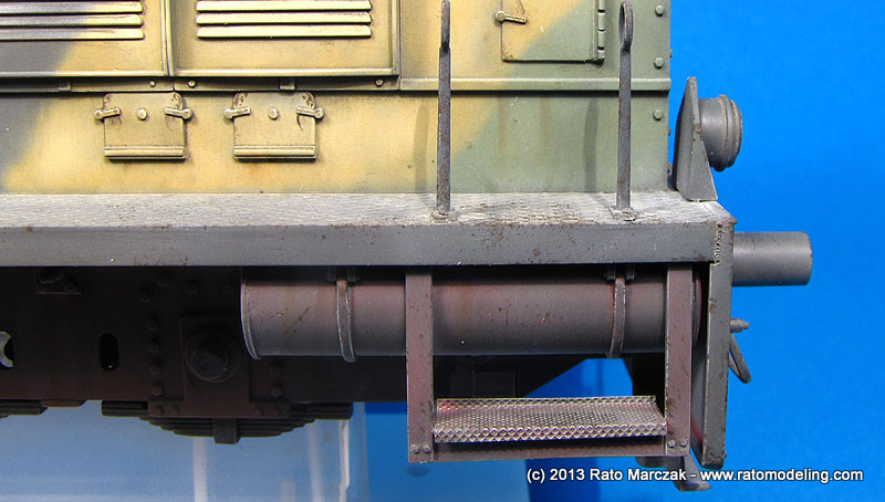
Trumpeter provided nice PE anti-slip metal sheets to be bent and used in all the stairs and steps of the model. Their use is straighforward, and they add a lot to the plastic parts:
The exception for which Trumpeter has not provided any PE detail is the hinged platform behind the cabin's rear door. I upgraded it with left-over PE parts simulating anti-slip sheet glued atop the kit part:
To finish off the control cabin, I added a gutter to the cabin's roof. It was just a matter of gluing plastic strips along the sides of the curved roof and sanding the edges to simulate a curved sheet:
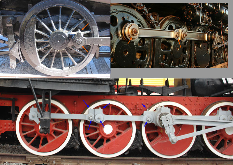
The wheels were assembled as per kit instructions, except that I decided not to glue them to the axles to make painting easier. However, most moving parts lack important details, in particular safety devices and lubricating accessories. Most of the movable parts have some kind of cap or plate to keep the lubricant from spilling out, and these are fixed in place by bolts. Since I don't know the exact terminology for these thing, the figure below shows some of these items common to old locomotives:
I took a shortcut and stashed circular disks to the shafts, maybe I'll add an hexagonal bolt later. The lubricant tub covers were made by rectangular plastic strips, with a small bolt glued atop of it:
After a halt of several weeks, I resumed work on the project. To keep some interest on it, I had to paint something, so I started with an easy thing: the radiator of the diesel engine. Nothing fancy. Some black, dark gray and steel paint, black washes and lots of drybrushing:
Contrary to my initial thought, much of the radiator could be seen through the front grille. I cemented the radiator in place, protected it with pieces of post-it notes and glued the engine cover in place. The post-it notes will protect the radiator during the whole assembly, and eventually removed throughout the grille openings. If you are assembling this model, don't forget to paint the interior of the engine cover with a dark color, because you can see a lot through the grille.
Looking around to see what I was missing to finish off the locomotive, it became clear that there wasn't much left in the sprues, and so I decided it was time to paint and assemble the conductor's cabin. I started by the floor, but soon I realized that there was a small color puzzle to solve first: which ones should be the colors of the cabin's interior? With my limited info on the subject, I reasoned that most things should be painted with the same color of the exterior camouflage, i.e. panzer gray, but it also seemed correct to leave the control bench painted in black like most engines during their civil life prior the war.
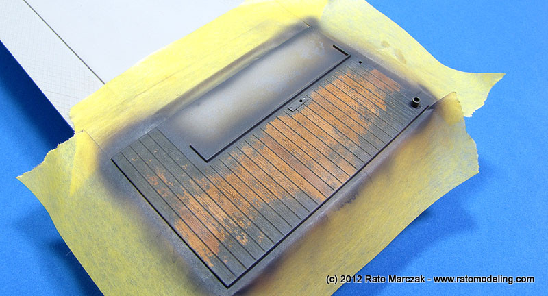
Back to the floor, the real thing was wood planked, and it would be a nice chance to use the now popular hairspray technique to simulate chipped paint. I started painting the planking with two or three shades of wood, then shot a protective layer of automotive clear gloss lacquer, and finally coated everything with a good layer of the cheapest hairspray I found in the mall:
After waiting the hairspray to dry, I shot a coat of Tamiya German Gray XF-63 acrylics and dried it right after using a hair dryer. And then the fun started: I soaked the whole area with tap water and started to scrub the acrylics with a short flat brush. The wetted hairspray layer will make the paint above it to peel off easily (I'm currently writing an article explaining the method - stay tuned). I reasoned the German Gray color would flake off from the planking more heavily along trails connecting the doors. That's why I removed almost all paint from these areas:
I liked the effect, with some paint remaining along the deeper wood grain marks and into the crevices between each plank. I sealed everything with another coat of gloss varninsh and applied a Burnt Sienna oil wash to simulate grime and stains. A final coat of flat varnish sealed the wash and after that I drybrushed a light cream yellow oil to highlight the wood grain and reduce the contrast between wood colors:
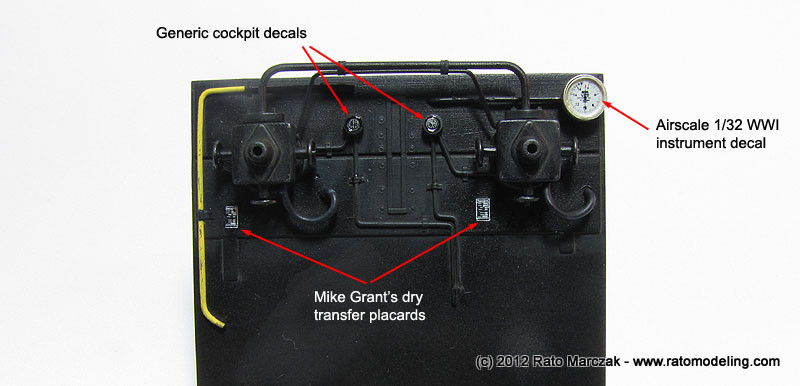
The next obvious painting section was the conductor's bench and its 'control panel'. I was willing to paint those parts, but I had to hold any multi-color thoughts after checking many photos I took while visiting the Railroad Museum of Pennsylvania, because these spaces were not full of color. Instead, most of the times they are just plain black, except for a few important devices like emergency brakes, master pressure valves and the like. I airbrushed a solid layer of semi-gloss black automotive lacquer over the parts and, while the paint was still in the aibrush cup, added a few drops of white and went back to the parts to simulate fake shadows, lights and a few grimy spots.
The most fun part was to bring manometers, gauges, valves and all those typical gadgets to life. I used cockpit placards and instrument decals from various manufacturers and left over sheets to decorate them. Whenever I had a punch matching well the gauges' diameters, I'd cover the instrument with a thin clear disk to simulate the glass. Otherwise, I'd just apply a droplet of clear nail varnish. Both worked well, but nothing matchs the realism of a clear disk simulating gauges' glasses.
The same approach was used for the instruments on the conductor's bench. I think Trumpeter should have provided decals for them... To weather the area, dark gray paint was applied with a sponge along edges and corners, while Prismacolor gray pencils simulated scratches and small paint chipping. Graphite was used to bring some shine to recent scratches. Pin washes reproduced dust and dirt accumulated along edges. The final weathering step was to make a liberal use of Humbrol's Polished Steel (#27003) from their Metalcote line with both a pointed brush and sponges. I love this stuff, as they can be polished when dry, rendering the perfect 'exposed metal' look to the part.
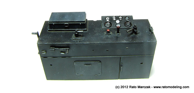
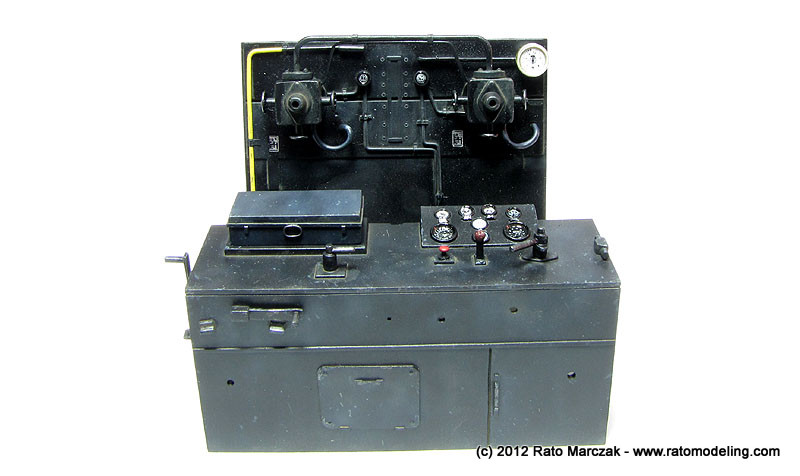
Here is a look of both assemblies together:
I deviated from the instructions at this point of the assembly. Since I had opened one of the cabin's door, it would be impossible to assemble the four cabin walls. Instead, I assembled the front and side walls using alignment tools to make the corners perfectly square. I would let this dry completely before attaching the back wall.
The cabin's roof are formed by two parts to be installed on the top of the cabin. It would be made removable to see the cabin's interior afterwards. And by the way, in the photos below the cabin still have a few details to be installed, besides the windows, of course:
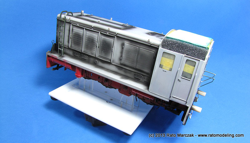
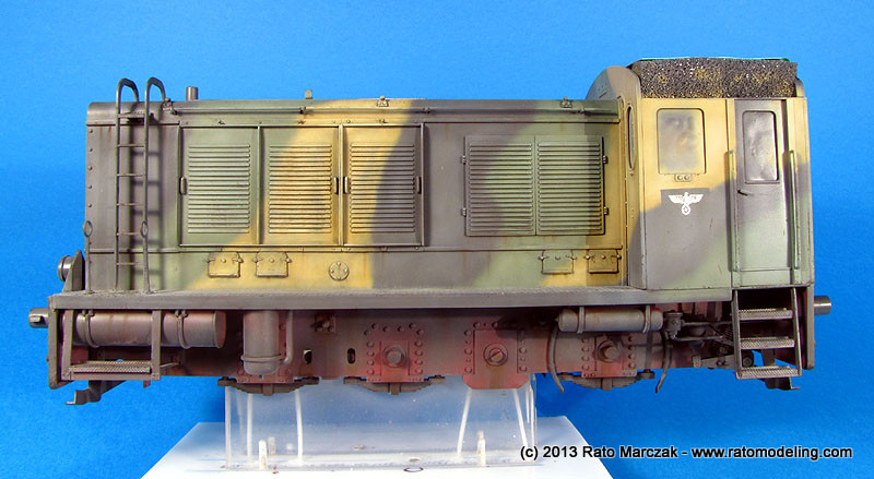
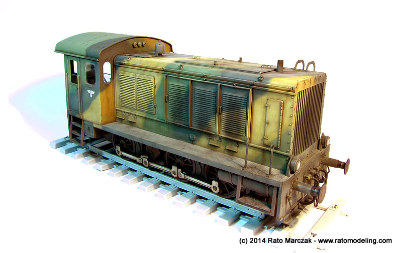
This is how the WR-360 stood a this point. Note the pre-shading already applied along the main body:
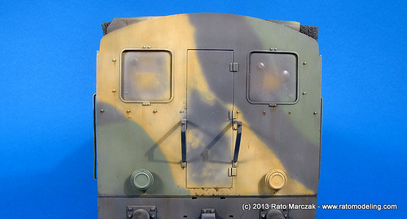
The back wall was simply painted dark gray and weathered with scratches here and there. To add interest, I glued a first aid box from a leftover PE set, right behind the conductor's seat. The reworked door was also painted using the hairspray method. Each door recieved a couple of handles, an opening handle and a window lowering handle:
A couple of extra details were added (a few wires) before the back wall was glued in place. Careful alignment was important, as I wanted to make the cabin's roof removable to show the interior. Handling the model started to become an issue, since there were several details to be assembled on the underside (not the mention the whole brake system and wheels), and holding the model by the engine cowling was not an option because of the fragile details cemented in place (see text below).
I ended up making a jig using bolted acrylic plates. The jig securely hold the model by two axles and, although not perfect, worked well:
With the application of the main camouflage color approaching, I temporarily assembled the doors and windows in place to serve as masks. The trick is to apply a good coat of Maskol (or similar) to the windows and fix them in place with tape on the inner side of the cabin. Once the external paint is finished, I would just pop the windows and doors out, remove the Maskol and glue them definitely in place. I blocked the cabin's ceiling with pieces of sponge and tape.
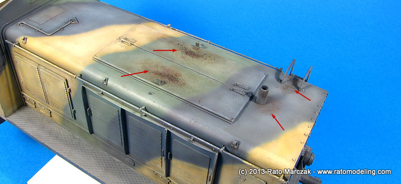
Other details added to the hull at that point were the engine panel lockers, which were scratchbuilt from plastic bits, and the characteristic hooks on top of the engine, used to lift the cowling. Trumpeter missed both, and the latter had a master scratchbuilt and copied six times in resin. Once glued in place, the hooks were decorated with Tichy Train bolts:
Another item which I really disliked in this kit are the side buffers of the engine. In my sample they had a visible mold shift, and these are the kind of part which never looks good without being perfectly cylindrical. Since it would be impossible to make them acceptable without reducing significantly their diameter, I opter for copying a brass item from Lion Roar (railroad flat buffer) in resin. They are workable, but all I wanted was the internal cylinder, which will later accept the buffers from the kit. The external cylinder was turned in my lathe, copied in resin, and glued to the front and rear plates in lieu of the kit parts. Once the main camouflage is finished, I would go back and install the movable parts of the buffers inside them:
Before loading my airbrush to apply the main camouflage color, I had to dig some further info about the WR-360, in particular the C-12 model. I found out that most of them (maybe all C-12s) were manufactured before the war, and only a dozen or so of them were actually produced before switching to the C-14 model, which was manufactured in much larger numbers. Supposedly, the C-12 never saw action outside the German borders, but I don't care that much (more on that later).
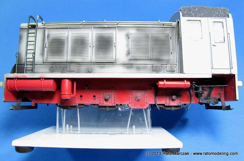
My point here is that before the war these engines had a less military aspect. I'm guessing that most of the WR-360 had their running area painted red like other locomotives usually are (and can be testified by color photos of the model C-14). When pressed into war service, a suitable camouflage would be in order, and I doubt the crews would disassemble such equipment just to apply a coat of Panzer Gray. Therefore, it seems reasonable that some of the red color on the underside of the engine could be seen through the panzer gray camouflage. That was the plan.
And so I started applying a solid layer of ATSF Red from Floquil railroad range - nothing could be more suitable, eh? I used the ATSF Red on the tanks and accessories too before gluing them in place. The scratchbuilt brake parts were painted red and black and cemented in place as well. These subassemblies were all painted separately and then installed because when the panzer gray color would be airbrushed, I didn't want it reaching the hidden areas of the lower engine, leaving a hint of the original red color there - just like what should happen with a crew man using a paint gun to camouflage the sides.
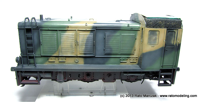
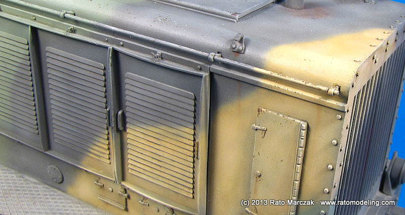
Once everything was dry (Floquil are enamels, taker more time than I'm used to), I painted the whole engine with Panzer Gray. While the paint was still in the airbrush cup, I added white and thinned the mix even more, and went back and applied highlights and fading here and there, particularly on the horizontal panels which should be more exposed to the sunlight and accumulated more dirt.
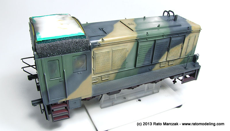
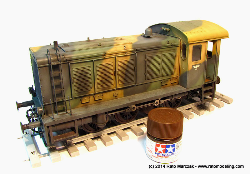
Then I started to apply the other camouflage colors. I used a mix of Tamiya's Dark Yellow and Deck Tan to make the tan color, while the Olivegrün (RAL 6003) is a mixture of Field Green and RLM 82 from automotive lacquers. I airbrushed both colors freehand using a Grex Genesis.XN airbrush. It was not a neat job, but I reasoned this was field applied cammo, in a rush, and using whatever paint was available (what good excuse, eh?). Of course I went back with a lighter version of the green and the tan and faded both to age them a bit as well...
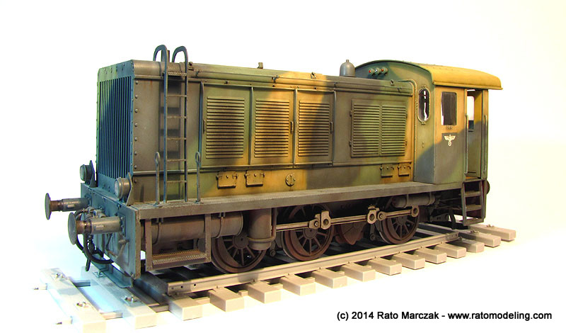
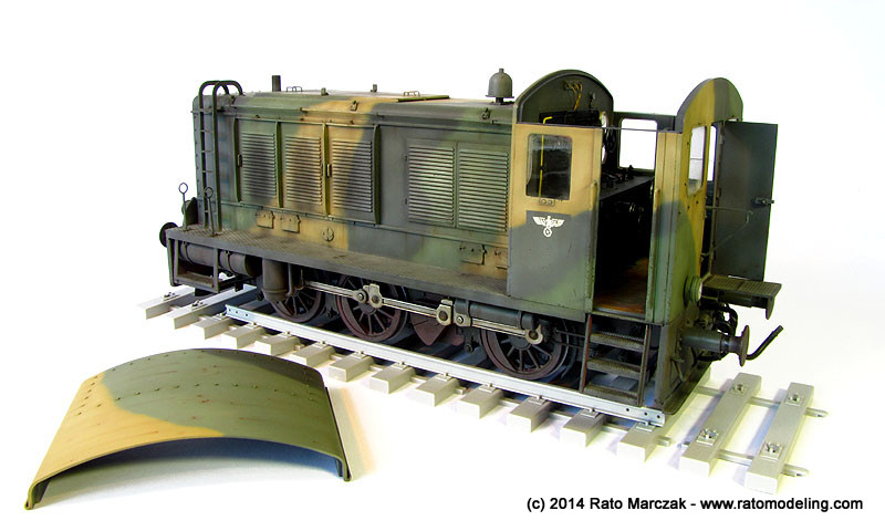
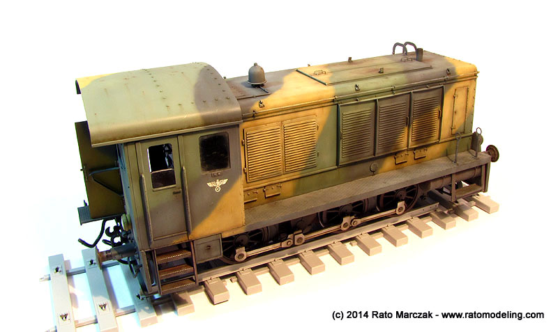
Here is how it was by then:
I failed to find any documentation about specs to camouflage these things, and understandably probably never will. So the colors and pattern where an educated guess, but I had some hints from a couple of railroad modelers and camouflage scheme from a Czech magazine.
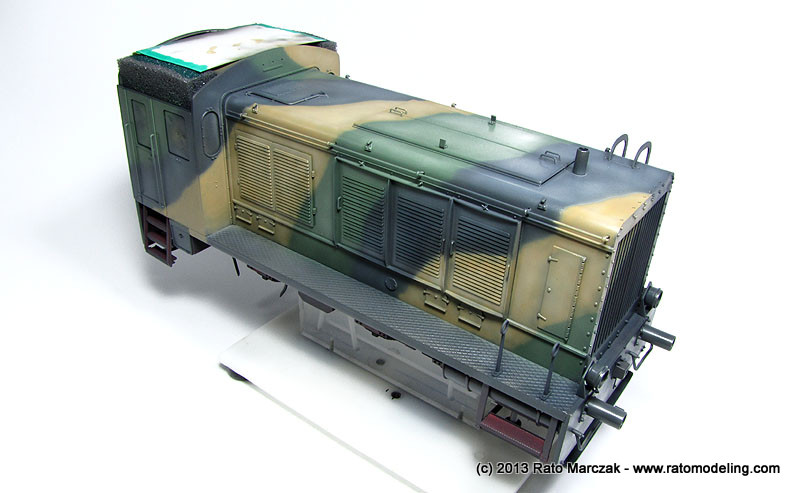
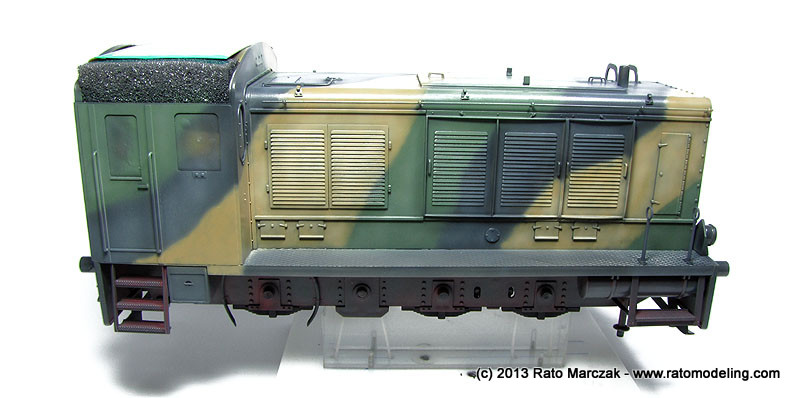
Here you can see how the red color was purposedly left visible at places to simulate a paint job made in a hurry:
And that's how it was:
After a long time working on other projects, I resumed the work on this model. Meanwhile, a great deal of time was spent reading about weathering techniques. Fortunately, we had endless resources and media on the subject, but still, it is a long learning curve on pigments, filters, washes, chipping and all that stuff that didn't exist last time when I finished a 1/35 model. I'm an old school modeler, and wanted to try some ready made products like washes and special effects.
I confess I was a bit afraid of ruining the model trying something new (to me), but I prefer to approach this phase being afraid of overdoing something than ending with those models which look like they remained 70 years under the mud... Fortunately, I made no serious mistakes, but during the process I had to constantly remind myself the goal of mildly weathering the WR-360, as an operational equipment which hasn't been submitted to much beating.
The basic steps I followed were as follows (I had to go back to some of them occasionally):
1. Airbrush further fading on selected areas using lighter mixes of the camouflage colors.
2. Apply filters using artists oils.
3. Apply flat coat followed by a gentle oils dry-brushing with lighter camouflage colors.
4. Apply pin washes using dark brown oils.
5. Simulate heavy dirt on the undersides.
6. General dusting using enamel paints.
7. Simulate leaks, streaks, and rain marks.
8. Simulate rusted areas using pigments and paint.
9. Paint chipping using a fine brush and acrylic paints.
10. Exposed metal simulated with powdered graphite or a pencil.
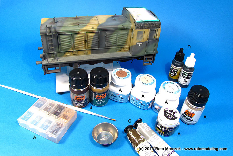
And the products primarily used for each step were:
A.
Grinded pastels and pigments (steps 5, 8 and 10): I used earth tones
for dirt and light earth for general dusting. Brands used for pigments
were AK, Mig and CMK. I used AK Dust Effects for the first time. I
tend to use CMK's pigments for mud and heavy dirt because their
pigments are visibly coarser than the other two. I also used pigments
for light rust effects.
B. Diluted enamel for effects (steps 6 and 7). I used AK Streaking Grime, Dust Effects, and oils.
C. Artists oils (steps 2, 3 and 4): Baically Natural Shadow, Gray, and Burnt Sienna oils.
D. Acrylic paint (step 9): Vallejo dark brown and dark grey mixes were used to simulate paint chipping.
B. Diluted enamel for effects (steps 6 and 7). I used AK Streaking Grime, Dust Effects, and oils.
C. Artists oils (steps 2, 3 and 4): Baically Natural Shadow, Gray, and Burnt Sienna oils.
D. Acrylic paint (step 9): Vallejo dark brown and dark grey mixes were used to simulate paint chipping.
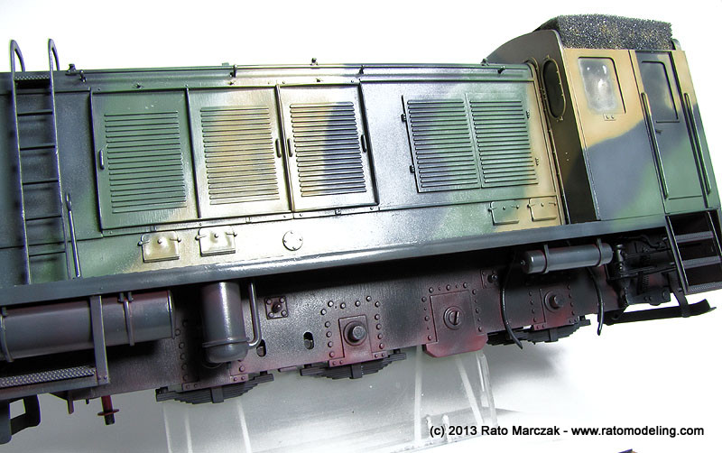
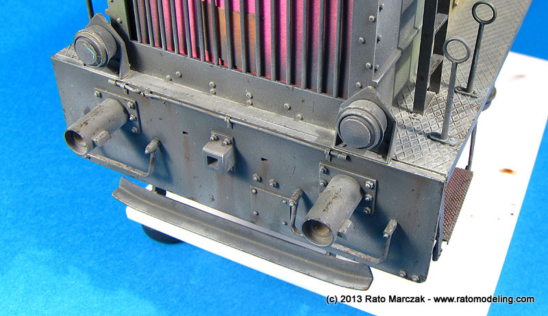
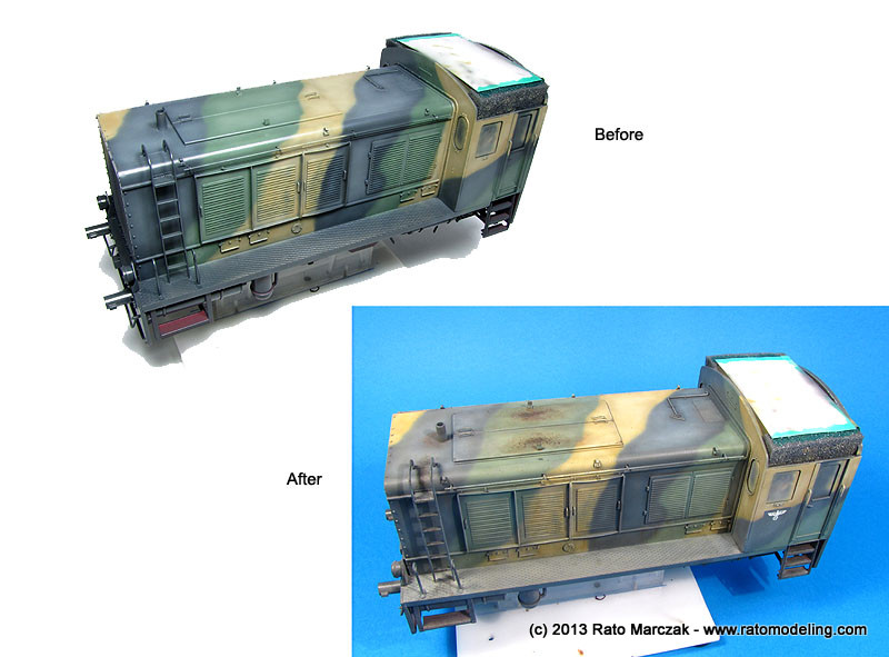
Step 7 was applied more heavily on the front and rear of the engine. They will be further enhanced later on, as I still have to install all the coupling devices:
Rain/light rust streaks were also applied under the windows, handles and panel joints. Step 6 was used on horizontal surfaces, particularly the catwalk on both sides of the engine compartment. At that point, all I did was to soad the catwalk with AK Dust Effects enamel. Later on these areas will receive chipping, scratching and oil marks:
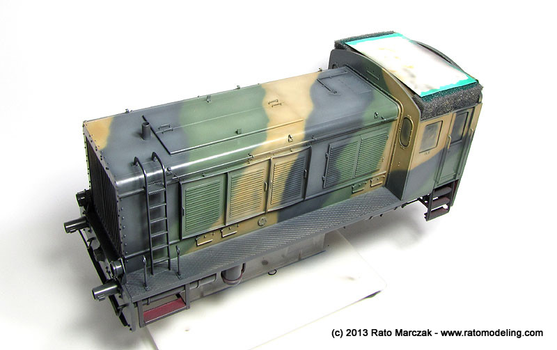
Step 8. On the top of the WR-360, I wanted to simulate a heavier rust effect, typical of areas where the metal panel presents a depression or sag, making the rain water accumulate and trigger the rusting process. I used the sponge method and acrylic paint to produce a gradation from light to dark rust colors. Pigments soaked in turpentine helped to blend everything.
I also used the sponge method to chip the paint in the ladder entries and around the chimney:
Step 9 is something that you have to do on several passes. On the first one, I used a fine pointed brush and Vallejo acrylics to produce chipping around areas with heavier use/traffic. At that point, I limited chipping to handles, corners, and ladders. I also chipped the paint under the engine, pressure vessels and piping. Those will be retouched later with a red pencil to reveal the red undercoat:
It is difficult sometimes to decide the order of the steps in order to not destroy the previous ones. It also requires good judgement to keep the balance, keeping in mind the severity of the weathering you want for the subject:
For insance, chipping on the top of the lights may sound strange at first, but it is possible that crew would step on it while servicing the engine. By alternating steps 6 and 9 you can simulate old or new chipping. Later, colored pencils will be used to enhance recent chipping with a lighter color of the camouflage:
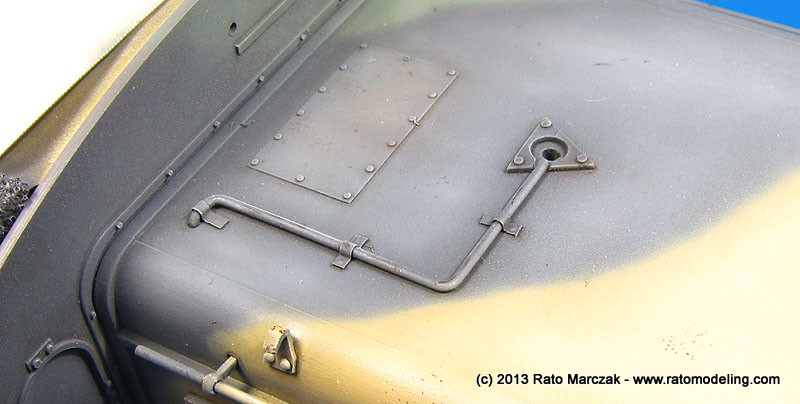
I
kept dry-brushing (step 6) to a minimum. Many modelers have abandoned
dry-brushing, but it is still a powerful and simple recipe to enhance
details, particularly when used with pin-washing and chipping. The
piping feeding the horn (below) is a good example, and the technique is
still unbeatable for enhancing bolts and rivets, in my opinion:
As expected, the washes, filters and effects darkened considerably the overall finish. And there will be no final flat coat on the model, which usually lighten the colors a bit (a final flat coat would weak considerably the effect produced by pigments). That's another reason why it is important to fade the camouflage colors to a good extent, even in larger scales such as 1/35:
As I said before, many of the steps may have to be reapeated as I proceed with the weathering.
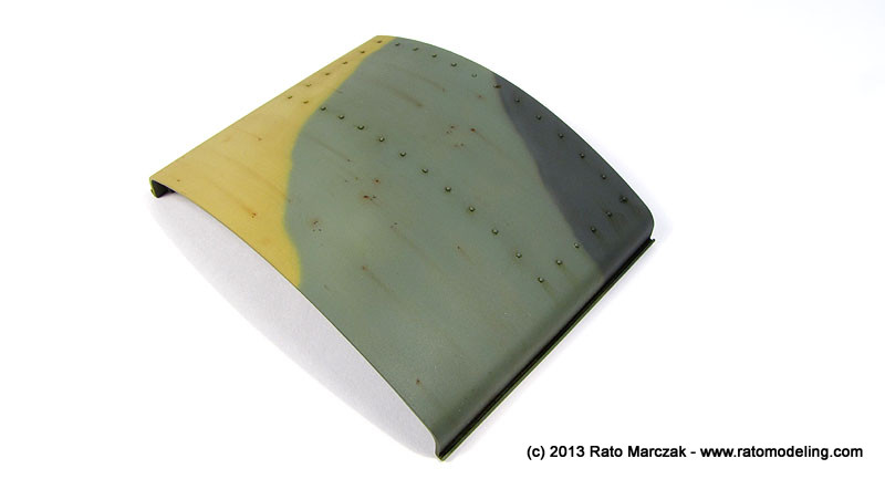
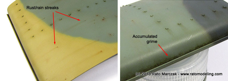
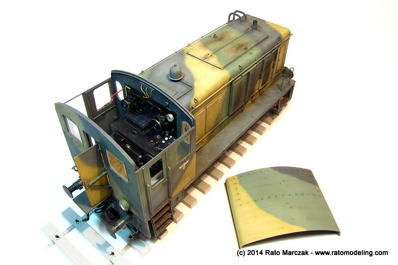
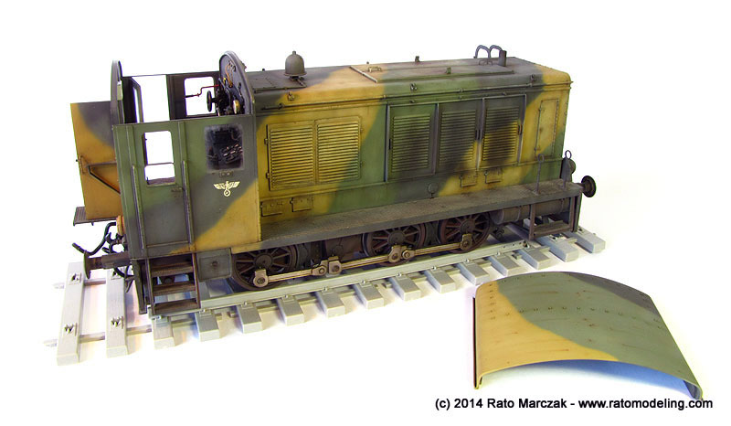
While I proceeded with the weathering on the engine body, I decided to use a different method to weather the conductor's cabin roof. I simulated rusted spots using paint, pigments and white spirit as usual, but instead of using dedicated fluids to simulate the corresponding streaks, I experimented using the pigments for that. It was just a matter of depositing a small amount of rust colored pigments on the starting points and dragging it downwards using a flat brush. It worked pretty well. However, I discovered that commercial pigments like AK and MiG may not be as intense as good quality pastel chalks are. Exactly the opposite of what is advertised by modeling pigments' manufacturers. Living and learning...
And while at it, I also simulated grime accumulated along the gutters playing with artists oils and white spirit.
On the bottom side of the roof, a lighting system was adapted using the kit parts. I turned a bulb from a piece of clear sprue and thermoformed a glass cover using acetate. A conduit was shaped to run from the side to the luminaire, and small pieces of aluminum foil formed the clamps. Judging from photos of other engines of the time, I suspect these roofs had a bare wood finish on the internal side... well, blame Trumpeter:
Trying to finish off the remaining details of the engine, I modified the kit lenses to accept stretched clear sprue mushroomed over a candle. They were painted with clear paints before being permanently attached to holes previously drilled. I don't have a clue whether the colors are correct or not:
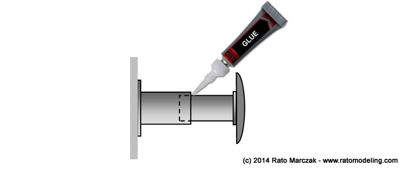
Still on the details of the engine, I had to finish the coupling system and the buffers. As mentioned above, kit parts C10 and C11 were replaced by two resin, improved ones. The outer cylinder of the buffers were glued to the front and rear plates of the chassis as you saw in the photos. The task then was to finish the movable parts of the buffers. The resin inner cylinder was cut to size and glued to the round and flat buffers (they alternate sides at the front and the rear of the engine). In order to do so, I installed the resin parts on a lathe and cut them to the correct length. I also turned a small step at the end of the cylinder to accept the kit's buffers, like in the instructions:
To weather the buffers/cylinders was a difficult task. Photos of railroad stock and engines show that if there is a part of the equipment that was not cared that much, they were the buffers - well, they are made to hit other buffers, afterall... My plan was to simulate buffers that were once overpainted with panzer grey and weathered heavily due to heavy work. So I applied factory color (black), then a light coat of panzer grey, and everything went out of control after that. Kidding aside, except for these two initial paint coats, everything was a bit of experiment to me, methods and sequence of application. The steps sequence I used were basically the following:
1. Primer
2. Semi-gloss black: this was a factory applied color. I used automotive semi-gloss paint to avoid the need of clear coats later and to resist to washes and weathering products.
3. Maskol: I used Maskol applied with a sponge over the buffers to make a heavy grey paint chipping (next step). Used on the buffers, only.
4. Panzer grey: this was the camouflage color that - I guessed - was overpainted on the engine when pressed into military service. I used a lightened version of Tamiya XF-63.
5. Paint chipping: the underneath Maskol was removed with a pencil eraser to show the black color.
6. Dry-brushing: Light grey oils were dry-brushed on steps and bolt heads, mostly on the back side of the buffers.
7. Dark rust: older rust spots were simulated using Vallejo paints and the dry-sponge method. The effect was applied on the front face of the buffers, trying to concentrate the effect on the perimeter of the disks, and also on the front part of the cylinders (Zone 2 - see text below).
8. Light rust: more recent rust spots like in step 6, except that I used a finer sponge and a more reddish color..
9. Dusting: light dust pigments thinned with Windex was generously applied over the parts. Once dry, excess was partially removed with a flat brush.
10. Exposed metal: Humbrol Polished Steel was applied with a sponge on the center areas of the buffers. This was necessary to simulate the effects of mechanical contact between buffers.
11. Metal pitting: Pitting was simulated by hitting a 6B pencil randomly over the buffers, producing tiny dark, yet metallic, spots.
At this point the buffers were virtually done. This was the result of these mere 11 steps:
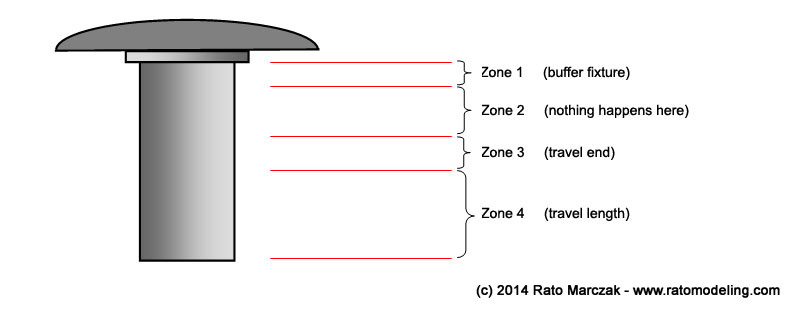
However, the cylinders still needed treatment. Since these are movable, lubricated parts, some reasoning is necessary. Under impact of another buffer, the buffer cylinder acts as a suspention, moving telescopically into the outer cylinder. Therefore, I devised four basic zones along the former:
- Zone 1 is basically the flange that connects the buffer to the cylinder. Therefore, it only collects dust and grime, and may show traces of the panzer grey.
- Zone 2 is the portion of the inner cylinder that never enters into the outer one. It may rust a bit, but may also show some remains of the polished steel due to grease stains.
- Zone 3 is the complicated one, because it marks the end of the travel length of the buffer system. Then, after some time in service, all the grease used to lubricate the cylinders end up in a messy smudge ring around zone 3, plus grime, dust, grass, deck cards, cigarette butts, engagement rings, you name it... Lost something? Try looking there!
- Zone 4 is the working length of the cylinder, which actually enters into the outer one during operation. It is common to apply grease in large quantities around this area, but most of it is pushed forth to Zone 3. The attrition between the cylinders and the lubricant make this zone mostly exposed metal.
So, how to weather these zones? This is what I did:
12. Dark dust: Further darker dusting diluted with Windex was applied on the back side of the buffers and Zone 1.
13. Exposed metal: Humbrol Polished Steel was dry-brushed circumferentially along Zone 4. This produced a faint metallic sheen randomly spread around the telescoping length of the cylinder.
Zone 2 was left as it was, but I still had to simulate the grease smudge on Zone 3.
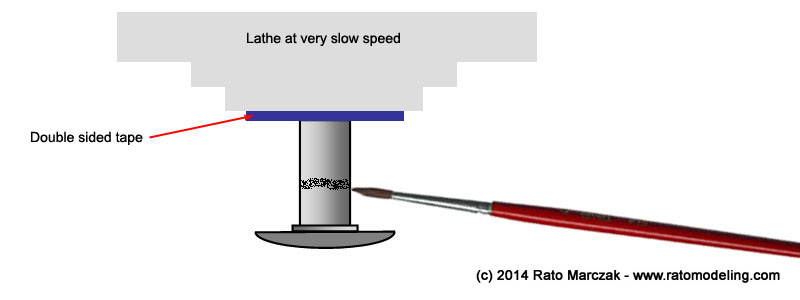
14. Grease smudge: In order replicate this effect on Zone 3, I installed a disk on my lathe covered with a double sided adhesive tape. This allowed me to mount the almost-finished buffers without the risk of damaging the painted areas. I prepared a mix of Tamiya Smoke (X-19) and Humbrol Smoke pigment and applied it with a brush while turning the lathe at minimum speed. By zigzagging the paintbrush just a tad you avoid a perfectly circular mark. Don't simply brush the mix, try dabbing the point of the paintbrush. In addition, small blobs of the smudge sometimes left the paintbrush, simulating larger spots of grease. The pigment made most of the X-19 sheen disappear, so I had to come back and apply gummy (partially dry) X-19 randomly with a toothpic around Zone 3 and the aft end of Zone 4. This resulted in a mix of old (semi-flat) and recent (gloss) grease simulation:
Once everything was dry, the finished buffers were glued in the outer cylinders:
And this was the result of steps 12-14:
The coupling mechanisms were next. I want them movable, at least the aft one, since it must connect the flatbed later. I used a method that master modeler Rodney Williams taught me. Basically, I drilled holes where the pins went and inserted a plastic rod which was 'mushroomed' by a lit incense (not a candle, as shown below):
I ended up using this method for all connector pins. The bolts & studs are brass items from Precision Harware. The parts were individually painted with semi-gloss black automotive lacquer, dusted with pigments and chipped with polished steel using a sponge.
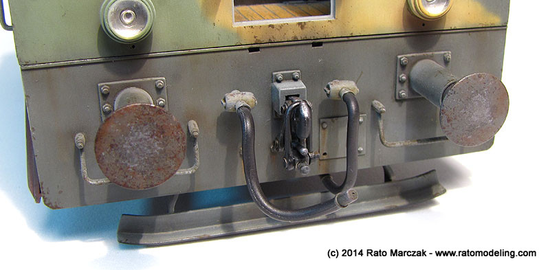
As you can see in the photos, the vacuum and steam hoses (parts C6) were painted and glued in place. An eagle eye will note that I bent the hoses slightly to make them look more natural. One of the hoses on the aft was replaced by an insulated wire of suitable diameter, so I can shape it to connect to the respective one in the flatbed later.
The masks of the lights were finally removed, revealing the bulbs made earlier with clear sprue. The traffic lights atop the cabin were glued in place, as well as the whistle.
And so I was finally on the last bits. The conductor's door was cemented open, and a crude lock was made from plastic bits. The little access platform was also glued in place, and unfortunately it hides part of the coupling details under it. All the windows were installed and light earth color pigments were powdered over them, then removed with a soft make-up brush, leaving accumulated dust around their borders. The window on the driving side was cut in about half its height to look like if it was lowered. I even simulated one of the windows cracked - it is a nice effect, but difficult to capture in the photos.
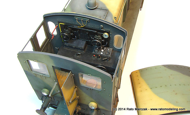
The lateral door was also installed in open position, but first I had to add a metal strip running over the top of both wall sections. This was glued with epoxy glue and is a necessary measure to adde stiffness to the assembly, particularly in the case of a removable roof. The atmospheric view of the cabin pleased me, I just hoped I had taken the photos under natural light:
When processing these photos I noted that I forgot to install the electrical cables of all four lights. The holes and conduits are there, but the next time you will see the model will probably be during the diorama construction:
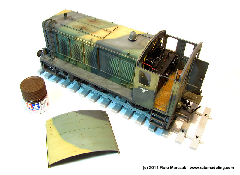
All the work on the brake system also payed off, albeit hidden under the ladder, it was a real improvement over the kit parts. The movable parts of the wheels should be a tad more greased to my taste, maybe I'll add more later:
I still have to add scratchs and chipped paint revealing the red color under the camouflage. This will be done with a colored pencil later on. For now, I can call it done:
The removable roof doesn't seem a so good idea now... The fit is so tight that everytime I remove/put it back I'm afraid some paint will be damaged. So far so good. Anyway it would not make any sense in not allowing to see all the details in the cabin:
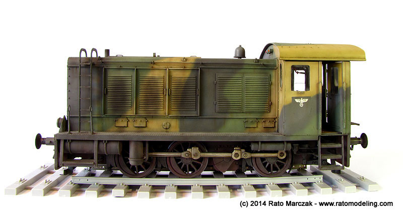
In the next installment, I'll just add a couple of shots showing the red paint scratches and the electrical connections, maybe. For now, these are the final photos of this long project:
/
| Technical file | |
| Kit:
|
-
Trumpeter #0216 |
| Additions:
|
|
| Basic
colors: |
-
Primer: automotive gray primer. - Semi-gloss and gloss black: automotive lacquer. - Flat black: Floquil Engine Black (#60106) enamel and Tamiya XF-1. - Dark gray: Tamiya XF-63 German Gray and automotive lacquers. - Red: Floquil ATSF Red (#110176) - Wood color: various Vallejo and Andrea acrylic paints. - Olivegrün: custom mix of automotive lacquers. - Tan: 50% Tamiya XF-55 Deck Tan + 50% Tamiya XF-60 Dark Yellow |
| Notes: |
-
Several scratchbuilt details (see text). |
Rato Marczak © 2014
